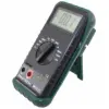
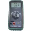
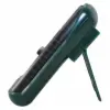
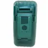
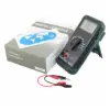
LC Meter,Digital Capacitance and Inductance Tester (only $28.95!) (CSI6243)
Price: $28.95
Save 40.9%!
43 IN STOCK
The CSI6243 Digital Capacitance and Inductance Tester features a large 3.5 digit LCD display and 10 total ranges (6 ranges for capacitors and 4 ranges for inductors). Also supplied with a rubber holster and safety design test leads. Highly accurate with Auto-Zero adjust and overload indication. A very handy piece of test equipment for general trouble shooting and component testing.
Features
Technical Specifications
L/C Ranges:
2nF, 20nF, 200nF, 2µF, 20µF, 200µF, 2mH, 20mH, 200mH, 2H
Basic Accuracy:
L: ±1.5% (<0.5µF)
±2.0% (>0.5µF)
C: ±2.0% (<0.5µH)
±5.0% (>0.5µH)
Dimensions: 86mm x 180mm x 38mm
Battery: Standard 9V
Technical Specifications
L/C Ranges:
2nF, 20nF, 200nF, 2µF, 20µF, 200µF, 2mH, 20mH, 200mH, 2H
Basic Accuracy:
L: ±1.5% (<0.5µF)
±2.0% (>0.5µF)
C: ±2.0% (<0.5µH)
±5.0% (>0.5µH)
Dimensions: 86mm x 180mm x 38mm
Battery: Standard 9V
Electrical Specifications
Temperature Coefficient:
Inductance: Range 2mH, 20mH, 200mH; 0.2%/°C. Range 2H 0.5%/°C.
Capacitance: Range 2nF, 20nF, 200nF; 0.1%/°C. Range 2µF, 20µF, 200µF 0.2%/°C.
This LC meter is intended for measuring the capacitance value of a capacitor and the inductance value of an inductor. It is not intended for determining the "Q" factor. As the measuring frequency is only 900Hz, this meter is not suitable for measuring inductors which are used in the high frequency circuit. In such a case, misleading readings may be obtained.
When measuring components within circuit, that circuit must be switched off and de-energized before connecting the test leads.
The CSI6243 Digital Capacitance and Inductance Tester features a large 3.5 digit LCD display and 10 total ranges (6 ranges for capacitors and 4 ranges for inductors). Also supplied with a rubber holster and safety design test leads. Highly accurate with Auto-Zero adjust and overload indication. A very handy piece of test equipment for general trouble shooting and component testing.
Features
- 3-1/2 digit, 21mm LCD with a max reading of 1999
- 6 capacitor ranges/up to 200µF
- 4 inductive ranges/up to 2H
- Auto zero-adjustment, high accuracy
- Overload indication feature
Technical Specifications
L/C Ranges:
2nF, 20nF, 200nF, 2µF, 20µF, 200µF, 2mH, 20mH, 200mH, 2H
Basic Accuracy:
L: ±1.5% (<0.5µF)
±2.0% (>0.5µF)
C: ±2.0% (<0.5µH)
±5.0% (>0.5µH)
Dimensions: 86mm x 180mm x 38mm
Battery: Standard 9V
Technical Specifications
L/C Ranges:
2nF, 20nF, 200nF, 2µF, 20µF, 200µF, 2mH, 20mH, 200mH, 2H
Basic Accuracy:
L: ±1.5% (<0.5µF)
±2.0% (>0.5µF)
C: ±2.0% (<0.5µH)
±5.0% (>0.5µH)
Dimensions: 86mm x 180mm x 38mm
Battery: Standard 9V
Electrical Specifications
| L (inductance) | ||||
| Range | Resolution | Accuracy | Test Frequency | Current through inductance under test |
| 2mH | 1µH | ±2% of full scale ±1 digit | 900Hz | 150µA |
| 20mH | 10µH | ±2% of full scale ±1 digit | 900Hz | 150µA |
| 200mH | 100µH | ±2% of full scale ±1 digit | 900Hz | 150µA |
| 2H | 1mH | ±5% of full scale ±1 digit | 900Hz | 150µA |
| C (capacitance) | ||||
| Range | Resolution | Accuracy | Test Frequency | Voltage Across Capacitance Under Test |
| 2nF | 1pF | ±1% of full scale ±1 digit | 900Hz | 150mV |
| 20nF | 10pF | ±1% of full scale ±1 digit | 900Hz | 150mV |
| 200nF | 100pF | ±1% of full scale ±1 digit | 900Hz | 150mV |
| 2µF | 1000pF | ±2% of full scale ±1 digit | 900Hz | 150mV |
| 20µF | 0.01µF | ±2% of full scale ±1 digit | 90Hz | 150mV |
| 200µF | 0.1µF | ±2% of full scale ±1 digit | 90Hz | 15mV |
Temperature Coefficient:
Inductance: Range 2mH, 20mH, 200mH; 0.2%/°C. Range 2H 0.5%/°C.
Capacitance: Range 2nF, 20nF, 200nF; 0.1%/°C. Range 2µF, 20µF, 200µF 0.2%/°C.
This LC meter is intended for measuring the capacitance value of a capacitor and the inductance value of an inductor. It is not intended for determining the "Q" factor. As the measuring frequency is only 900Hz, this meter is not suitable for measuring inductors which are used in the high frequency circuit. In such a case, misleading readings may be obtained.
When measuring components within circuit, that circuit must be switched off and de-energized before connecting the test leads.
