Arduino prototyping: Countdown timer display on a powered breadboard
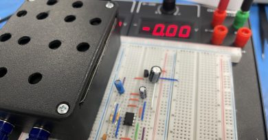
Arduino prototyping can be daunting if you’re new to electronics or programming. It doesn’t have to be though and in this simple project we built a seven segment display countdown timer using an Arduino Uno R3, a seven segment common cathode display, our powered breadboard, a 220 ohm resistor, and wire jumpers . This is a great project for learning more about Arduino prototyping if you’re new to using one and want to get some hands-on practice. We would rate this project as easy with little or no electronics or programming background required. We used the Arduino code provided in the Instructable Seven Segment Display Tutorial in order to perform the countdown. You could easily extend this project to other needs and further arduino prototyping of other types of timers and circuits.
In order to complete this project as we did you’ll need to perform the following:
- Connect segments A-G to digital output pins 2-8 on the Arduino Uno respectively (segment A to pin 2, segment B to pin 3, etc). You can determine which line segment corresponds to which pin using our pin out diagram on the seven segment display spec sheet (or by supplying 5V to test each segment and using the guide below). You will also connect pin Dp on the display to digital out 9.
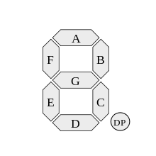
- Next you will connect the two common grounds on the cathode display to the 220 ohm resistor then connect that resistor to ground on the powered breadboard.
- Once it is all wired you will upload the code below to your Arduino Uno Board and then set your powered breadboard to 5V and power tie the breadboard into the 5V and ground terminals of the Arduino Uno. (For more information on getting start with an Arduino see Arduino’s getting started guide here)
- The countdown timer will now begin a countdown from 9 to 0, then it will immediately self destruct ?(just kidding). You can adjust the speed and functions in the Arduino code.
Hopefully you’ve learned a bit more about seven segment displays, prototyping, and the convenience of our powered breadboards. See our countdown in the animated picture below.
// Define the LED digit patters, from 0 – 9
// Note that these patterns are for common cathode displays
// For common anode displays, change the 1’s to 0’s and 0’s to 1’s
// 1 = LED on, 0 = LED off, in this order:
// Arduino pin: 2,3,4,5,6,7,8
byte seven_seg_digits[10][7] = { { 1,1,1,1,1,1,0 }, // = 0
{ 0,1,1,0,0,0,0 }, // = 1
{ 1,1,0,1,1,0,1 }, // = 2
{ 1,1,1,1,0,0,1 }, // = 3
{ 0,1,1,0,0,1,1 }, // = 4
{ 1,0,1,1,0,1,1 }, // = 5
{ 1,0,1,1,1,1,1 }, // = 6
{ 1,1,1,0,0,0,0 }, // = 7
{ 1,1,1,1,1,1,1 }, // = 8
{ 1,1,1,0,0,1,1 } // = 9
};
void setup() {
pinMode(2, OUTPUT);
pinMode(3, OUTPUT);
pinMode(4, OUTPUT);
pinMode(5, OUTPUT);
pinMode(6, OUTPUT);
pinMode(7, OUTPUT);
pinMode(8, OUTPUT);
pinMode(9, OUTPUT);
writeDot(0); // start with the “dot” off
}
void writeDot(byte dot) {
digitalWrite(9, dot);
}
void sevenSegWrite(byte digit) {
byte pin = 2;
for (byte segCount = 0; segCount < 7; ++segCount) {
digitalWrite(pin, seven_seg_digits[digit][segCount]);
++pin;
}
}
void loop() {
for (byte count = 10; count > 0; –count) {
delay(1000);
sevenSegWrite(count – 1);
if (count == 1){
writeDot(1);
}
}
delay(2000);
writeDot(0);
}