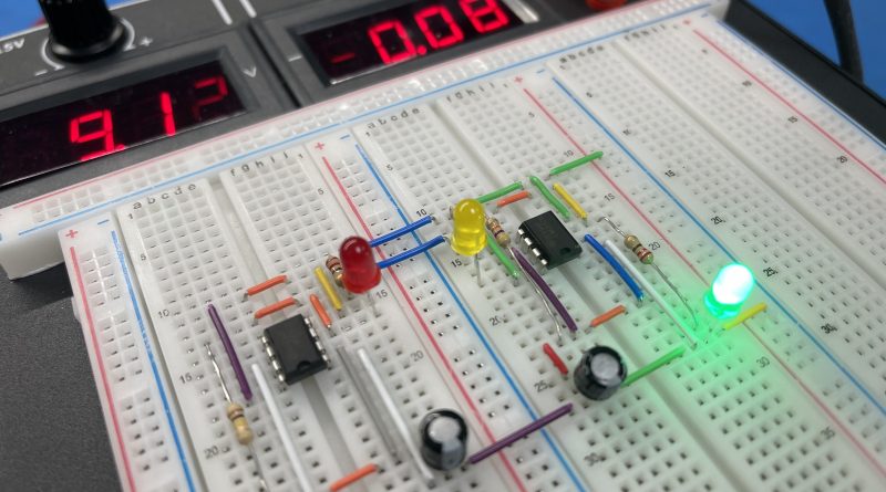
Model Traffic Lights on PBB-272B
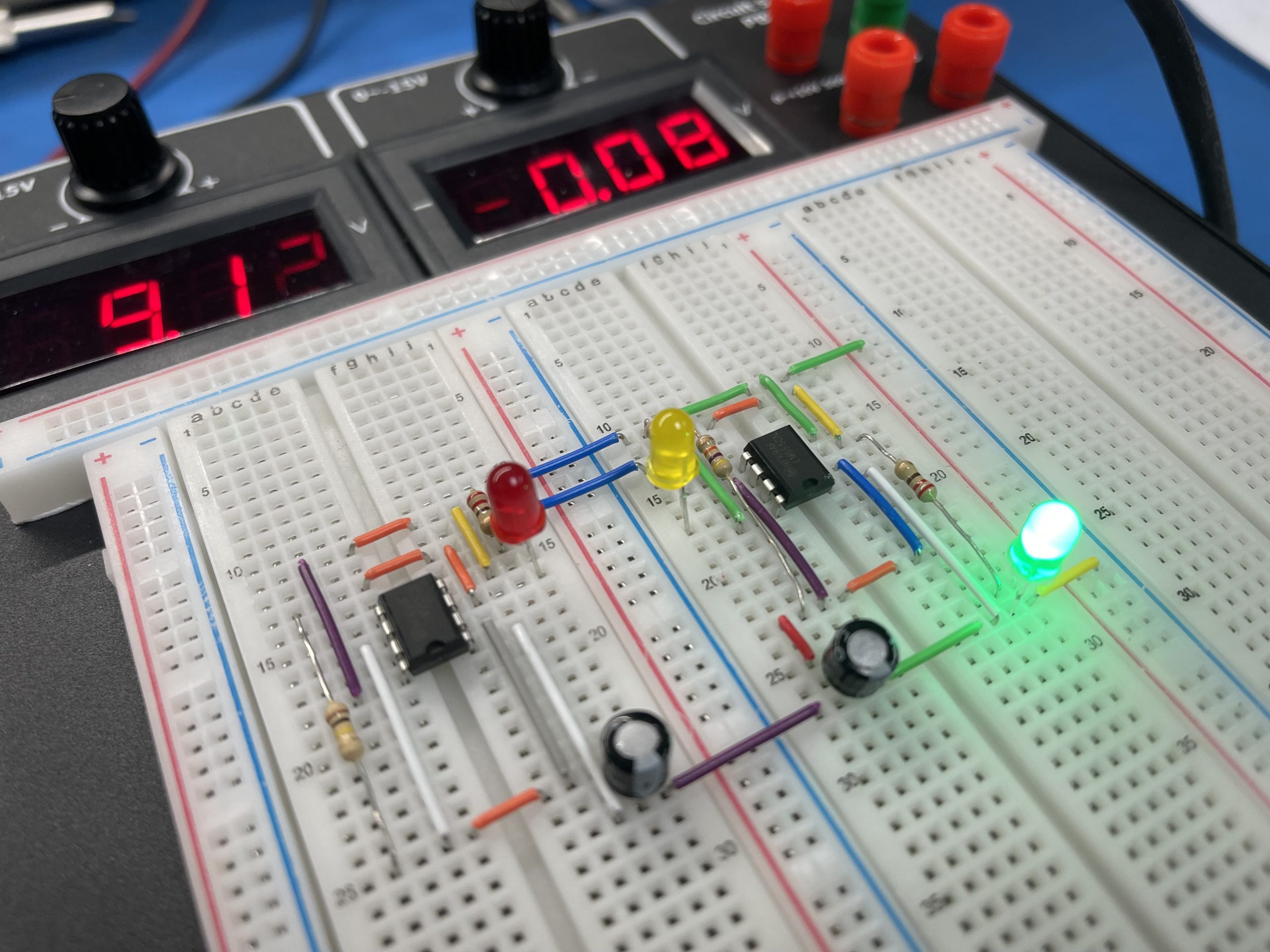
Let’s take it back to basic by modeling the traffic lights circuit on a Powered Breadboard PBB-272B and with a few other electronics components. This circuit turns ON the green LED, keeps it ON for some time, then turns ON the yellow LED for a moment, and finally turns ON the red LED for almost the same duration as the green LED. This cycle again starts from the green LED.
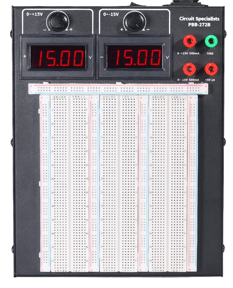
We are going to use the Power Breadboard PBB-272B to help us with this project. The PBB-272B is a very useful tool that any Makers, Circuit Board designer, and college labs should have for prototyping. The PBB-272B provides a 0 to 15V output port tight on top for easy access and a large readout with high-level accuracy for what it is. Furthermore, the unit also provides 0 to -15V for the experiment that requires a stable negative voltage.
Table of Content
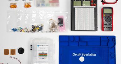
- Part List
- Circuit Diagram
- How This Circuit Works
- Logic Break Down
- Conclusion
Part List
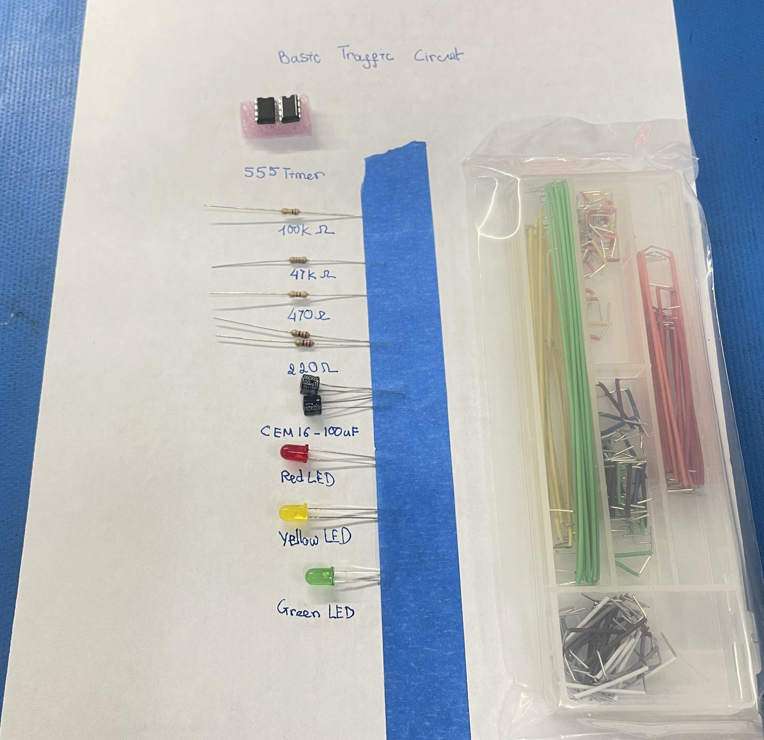
- Traffic Light kit Or
- 2 x 555 Timer ICs
- LEDs: 1 Red, 1 Yellow, 1 Green
- Resistors: 100K, 47K, 470R, 2*220R
- Capacitors: 2 x 100uF
- Power Breadboard PBB-272B
- Wire Jumper Kit
Circuit Diagram
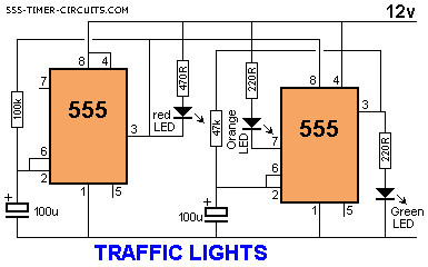
How This Circuit Works?
Here we have used two such astable circuits with the first astable circuit powering the other. So the second 555 timer IC will be powered only if the output of the first 555 timers IC is ON.
The red LED is connected such that it turns ON only if the output of the first 555 timers IC is at 0V. This is because the other terminal of the red LED is connected to positive voltage. Yellow LED turns ON during discharge mode of second 555 IC, and the green LED turns ON whenever the output of second 555 timer IC is at positive voltage.
Logic Break Down
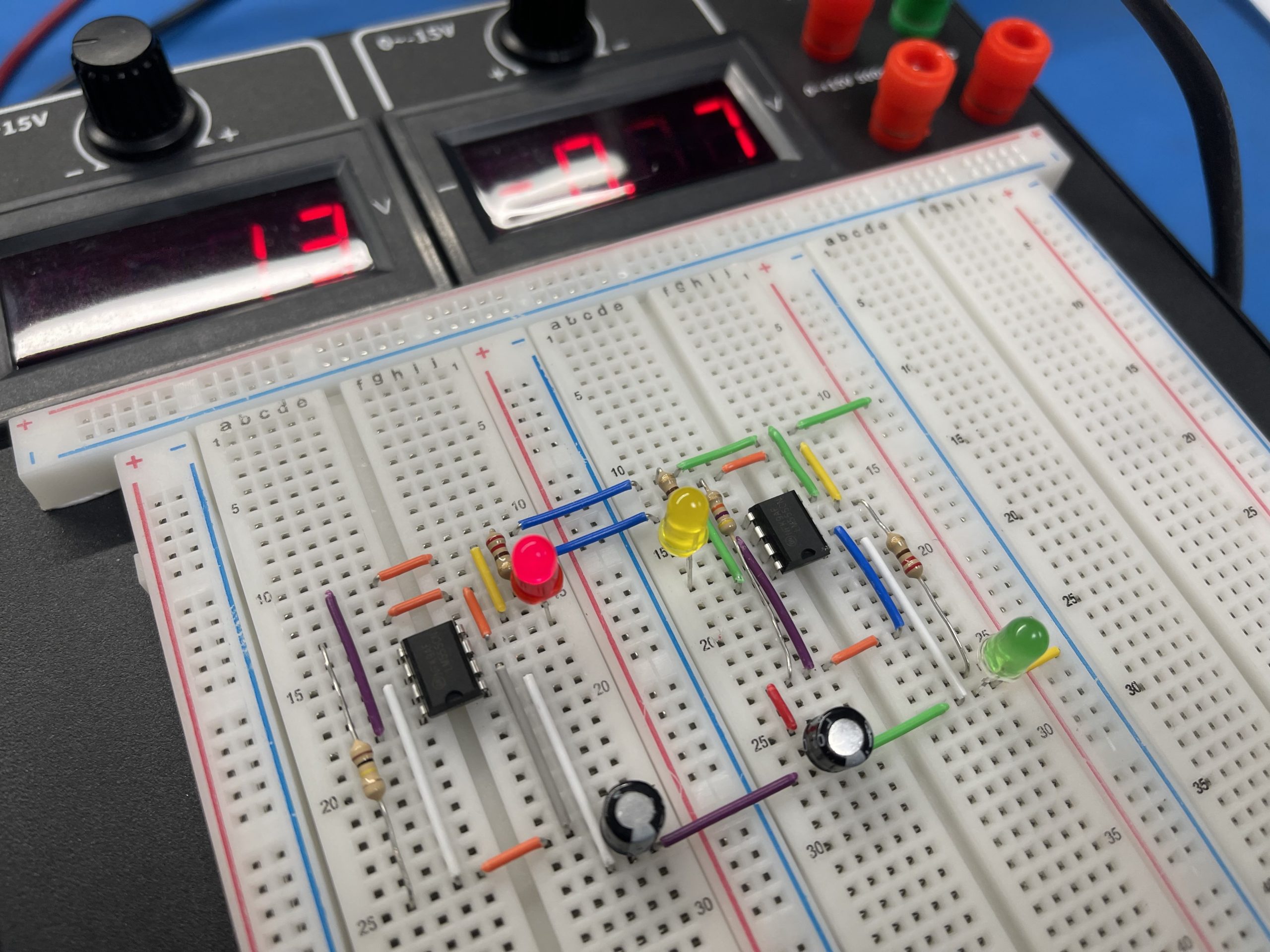
Immediately after we power ON this circuit, the output of the first 555 timer IC will be in ON state because the voltage at PIN-3 (Trigger Pin) is less than 1/3rd of the supply voltage. The red LED cannot turn ON yet, but the second 555 IC is powered and so the green light turns ON.
The capacitor of the 2nd 555 timer IC slowly charges and as soon as it charges to 2/3rd of the supply voltage (Threshold Voltage), the output of the 2nd 555 IC turns OFF and the yellow LED glows because the discharge pin is activated.
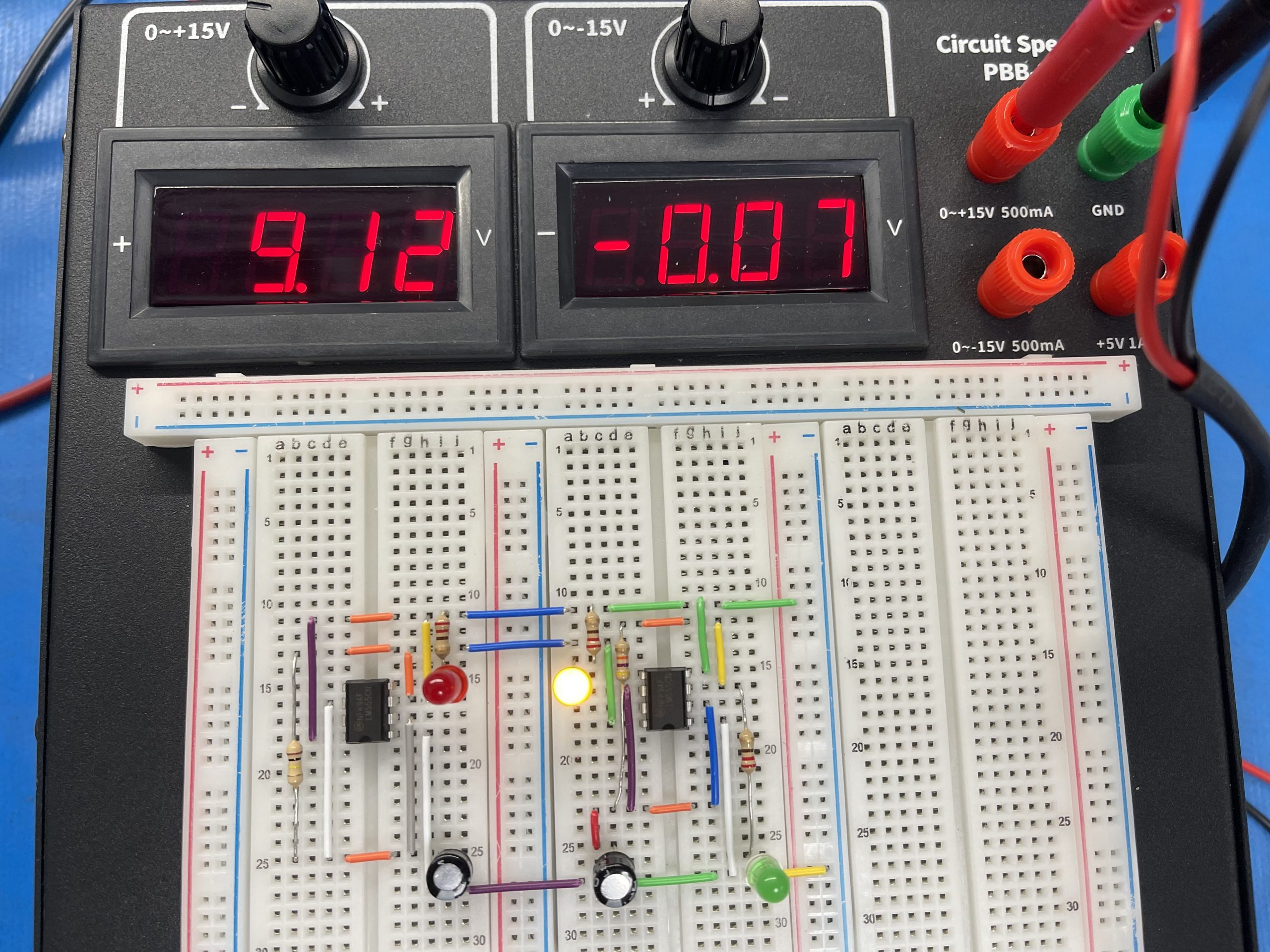
Normally the yellow LED would turn ON for the same time as the green LED. But even before the capacitor of 2nd 555 timer IC reaches 1/3rd of supply voltage, the voltage across capacitor of 1st 555 timer IC reaches 2/3rds of the supply voltage and so the output of 1st 555 IC turns OFF, resulting in yellow LED turning OFF and the red LED turns ON. The Cyle repeat with Red On.
Conclusion
This circuit turns ON the green LED, keeps it ON for some time, then turns ON the yellow LED for a moment, and finally turns ON the red LED for almost the same duration as the green LED. This cycle again starts from the green LED. It sounds simple enough with a Microcontroller, however not every project needs a microcontroller. Take back to basic help us understand the theory on how this legendary CHIP works its magic!