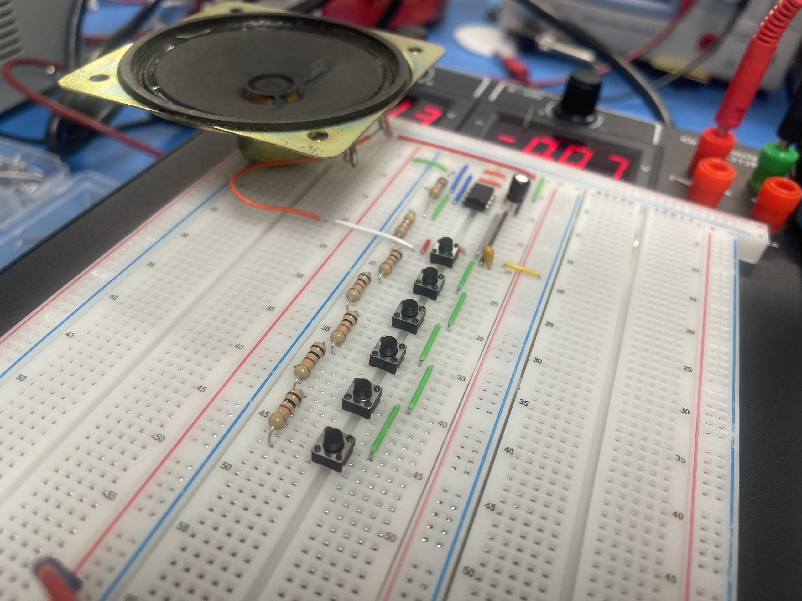
Build an Electric Piano Circuit on PBB-272B
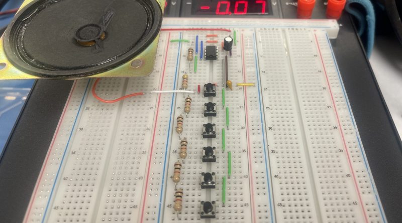
Let’s build an Electric Piano Circuit on the Powered Breadboard PBB-272B, it might sound hard but it’s actually very simple with the help of a 555 timer. We hope this tutorial on how to Build an Electric Piano Circuit on PBB-272B will make it easier for you to complete. This circuit consists of a number of push-button switches that produce sounds with different tones via a speaker.
The frequency of the output tones can also be fine-tuned by calculating the precise values of resistors to use. The formula for calculating the frequency is included in the explanation section of this tutorial.
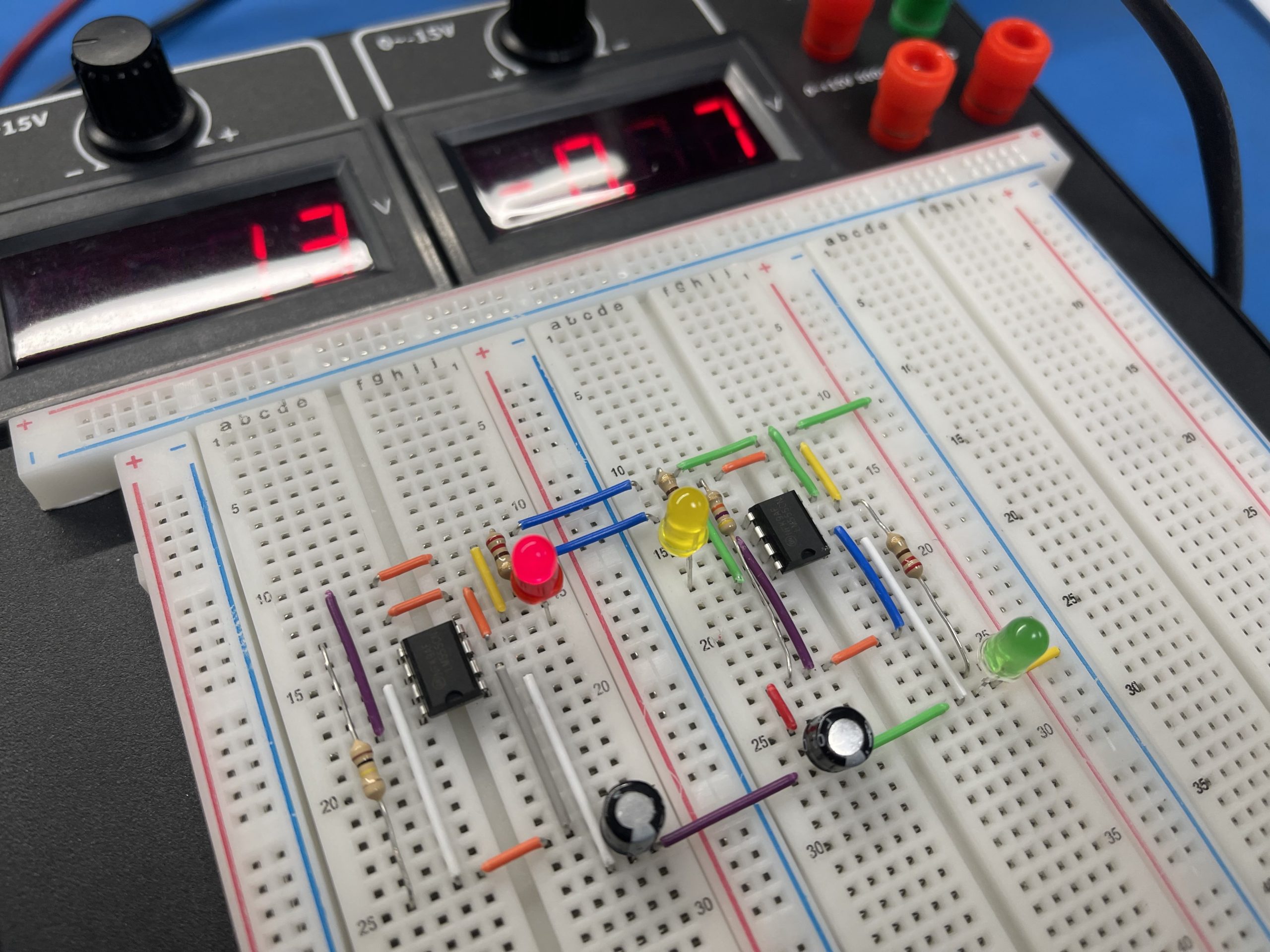
We are going to use the Power Breadboard PBB-272B to help us with this project. The PBB-272B is a very useful tool that any Makers, Circuit Board designer, and college labs should have for prototyping. The PBB-272B provides a 0 to 15V output port tight on top for easy access and a large readout with high-level accuracy for what it is. Furthermore, the unit also provides 0 to -15V for the experiment that requires a stable negative voltage.
Table of Content
- Part List
- Circuit Diagram
- How This Circuit Works
- Frequency Caculation
- Conclusion
Part List
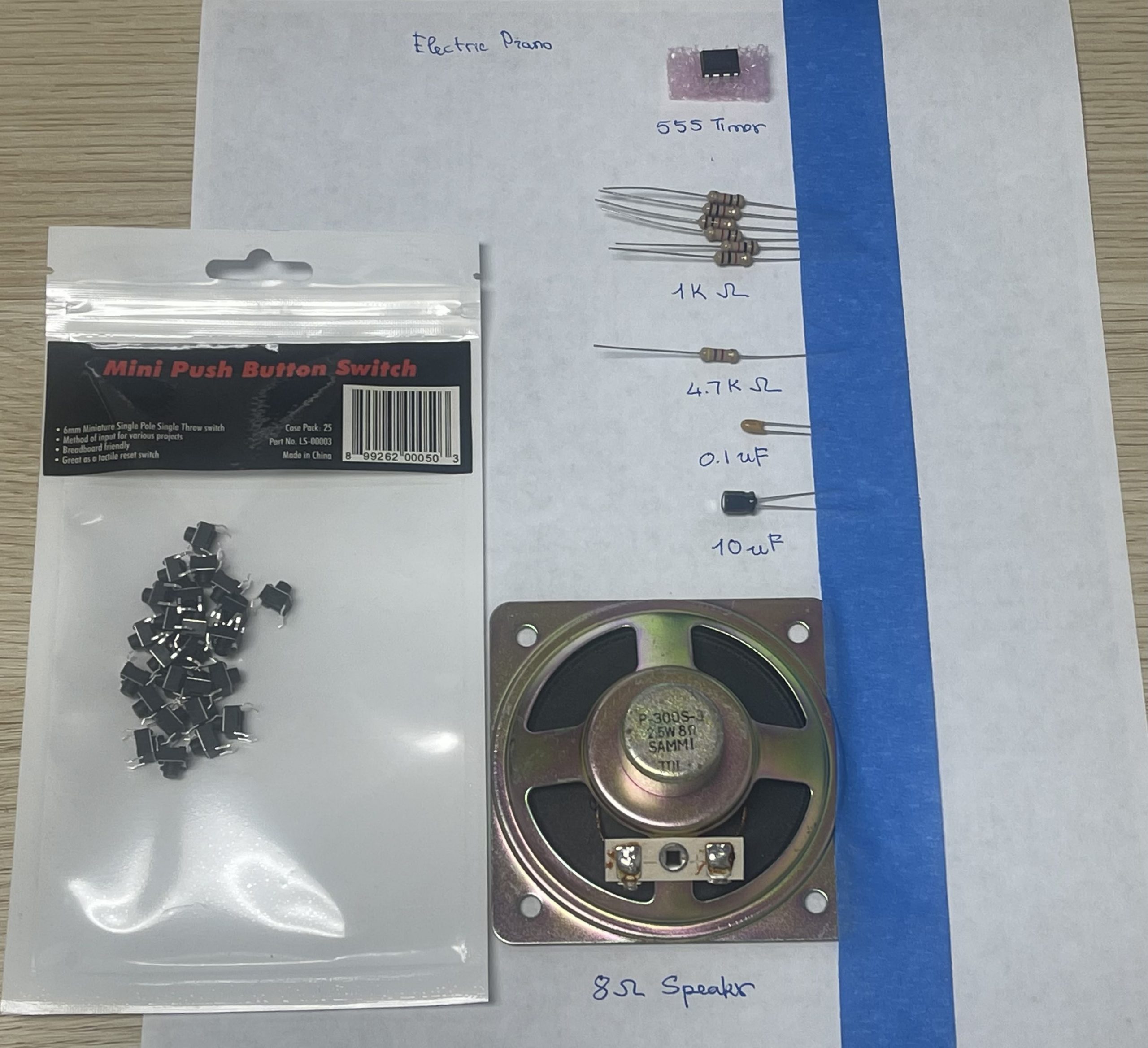
- 555 Timer IC
- 8 Ohm Speaker
- Momentary Push Button Switches
- Capacitors: 100nF, 10uF
- Resistors: 6 x 1Kohm, 4.7Kohm
- Power Breadboard
Circuit Diagram
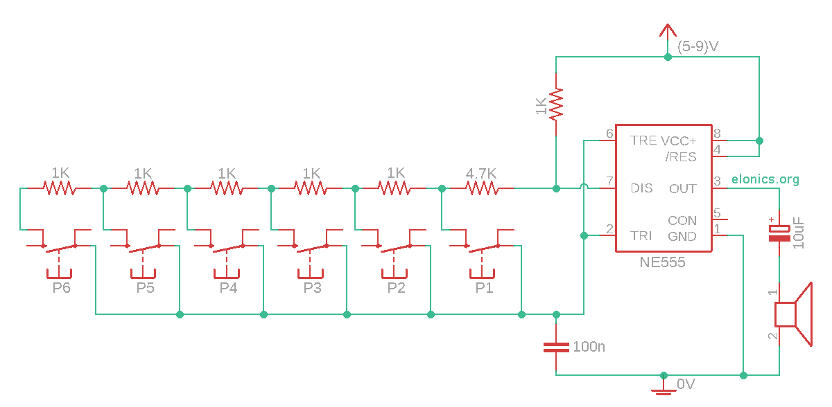
How This Circuit Works
Changing the value of the resistor in series with the capacitor changes the flashing rate (frequency). In addition, the relation is of inverse proportionality i.e, if the value of resistance in series to the capacitor is large, the frequency will be less, and vice versa.
Frequency Caculation
Formula for calculating the frequency of the output sound/tone:
Frequency (f) = 1.44 / ( (R1 + 2 * R2) x C1 )
In the circuit we made, the value of R1 is 1Kohm and C1 is 100nF. After replacing these values in the above formula, we have:
Frequency (f) = 1.44 / ( (1000 + 2 * R2) x 10-7 )
We can also rearrange the formula to calculate the value of resistor we need to use for any frequency required:
Resistance (R2) = ( ( 1.44 x 10⁷ ) / f ) – 500
Conclusion
Changing the value of the resistor in series with the capacitor changes the flashing rate (frequency). The frequency of the output tones can also be fine-tuned by calculating the precise values of resistors to use. This type of system is well suited for an analog circuit with a 555 timer, it would not be simple if one tries to use a microcontroller since the microcontroller then needs to output a specific frequency depending on which button is pressed, which could be a nightmare for programmers.