13 Commonly Used Components on PCBs for Beginners
PCBs are quite complicated devices that, upon first glance, can seem convoluted and intimidating. If you’re fairly new to casual electronic engineering, you might have come across it once or twice. In fact, you might already be familiar with it. But as a beginner, it’s definitely worth understanding the purpose of a PCB and knowing what you’ve got to work with before you attempt to construct your own.
So here’s our breakdown of the 13 most commonly used electronic components for PCBs.
What are PCBs?
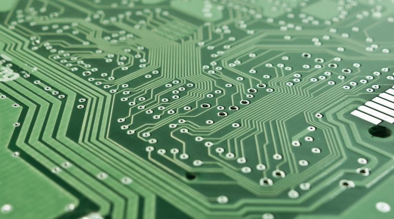
Printed circuit boards—or PCBs—can be considered the basic building block of any electronic design. A PCB board connects multiple electronic components to form one cohesive, fully functional system capable of powering different devices. Just like how whole cities are formed out of streets, subdivisions, districts, and buildings, so too do the components of PCBs interact. PCB boards have evolved over the years to play a crucial part in electrical engineers and hobbyists alike.
PCBs can range from single-sided boards (one copper layer only) to multi-sided (up to 20+ layers). The more layers added, the more complex the PCB, the more advanced the corresponding gadget it powers. More layers also mean more electronic components.
Robust PCBs can definitely hold upwards of a couple of dozen electronic components. For beginners, however, we recommend starting out with the 13 most common components.
- Resistors
- Capacitors
- Transformers
- Transistors
- Diodes
- Batteries
- Integrated Circuits
- Oscillators
- Inductors
- Switches/Relays
- Potentiometers
- SCR
- Sensors
Resistors – Control Energy
Resistors are the foundations of current control—which is why they’re so often used in PCBs. These two-ended electrical pieces are fairly simple to understand and integrate into different projects.
Resistance is often defined as the “ease” with which objects allow electricity to flow through them. Think of the difference between insulators and conductors; the former obviously possesses higher resistance than the latter.
Resistors, on the other hand, allow users to precisely define an object’s level of resistance. They are designed to resist the flow of an electric current by converting the electrical energy into heat—heat that is then dissipated.
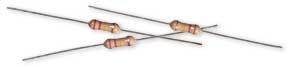
Resistors can be made of a wide range of materials and come in many different styles. The most common (and highly recommended for beginners) would be resistors made of carbon film in the axial style. Axial style resistors have leads on both ends of the rod. Their body is marked with different colored rings that represent the resistor’s resistance value.
Capacitors – Store Energy
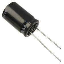
Outnumbered only by resistors, capacitors are electronic components you’ll definitely find on every PCB board. Whereas resistors control an electric charge, capacitors temporarily store it. Think of them as tiny batteries with even tinier storage space. They are capable of losing and gaining full charge in a split second. Because of this, capacitors are commonly used for “filtering:” a process where a backup source of energy takes over when the main source of power drops in order to not lose or reset data.
In PCBs, capacitors electrostatically store energy to later release it to wherever power is needed in the circuit. It works by collecting opposing charges (positive and negative) on two conductive plates (typically metal) with some form of insulating material between them.
There are different types of capacitors, often categorized by the conductive material of the plates or the insulating material that separates them. Most beginners and casual hobbyists use polyester capacitors, ceramic capacitors, or radial capacitors.
You’ll notice that some capacitors resemble resistors. The most telling difference is that resistors have leads on opposite ends. Capacitors have two leads protruding from the same side.
Transformers – Transfer Energy
General transformers transfer power from one source to another through a process called “induction.” PCB transformers function the same way. They transfer electrical energy from different circuits—and convert them—by increasing or decreasing the voltage. As with resistors, they technically regulate current. The biggest difference is that they provide more electrical isolation than controlled resistance by “transforming” the voltage.
PCB transformers consist of two or more separate inductive circuits (called windings) and a soft iron core. The primary winding is for the source circuit—or where the energy will come from—and the secondary winding is for the receiving circuit—where the energy is going to. Transformers break down large amounts of voltage into smaller, more manageable currents so as not to overload or overwork the equipment.
Transistors – Amplify Energy
Resistors may be fundamental to current control but transistors are fundamental to all modern electronics. They can, in fact, be considered the building blocks.
Contrary to storing, regulating, or controlling charges on the PCB, transistors amplify them. A bipolar transistor, which is the most common type of transistor, has three areas and three pins in which the current flows and is amplified. There are two types of bipolar transistors; NPN and PNP. Both are composed of the (1) base, (2) collector, and (3) emitter, and have both P-type areas and N-type areas.
- Base: base/foundation of the entire device
- Emitter: where the charges are released/emitted
- Collector: collects the charge carriers
An NPN bipolar transistor has a P-type area sandwiched between two N-type areas. In an NPN type, a small current flows from the base to the emitter. This current then turns on another circuit that causes a much larger current to flow from the collector to the emitter too, effectively increasing (or amplifying) the current that is released.
A PNP bipolar transistor has an N-type area sandwiched between two P-type areas. This reverses the NPN type’s current process. A small current starts at the collector and flows to the emitter, triggering a larger current to pass through the base and on to the emitter.
NPN transistors are more commonly used than PNP transistors for a number of reasons. However, both have their advantages and disadvantages depending on the project.
Diodes – Redirect Energy
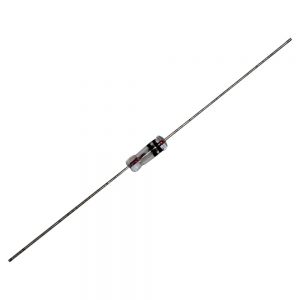
Going back to our PCB board – city comparison, diodes are basically the one-way streets on a printed circuit board. These two-terminal components control and redirect energy flow by allowing the current to flow down one direction and blocking it from moving down the other. The flow is typically from the positive terminal (called the anode) to the negative terminal (called the cathode).
Like resistors, diodes use electrical resistance to control the flow of energy. High resistance in one direction and zero resistance in the other effectively blocks the current from flowing in the wrong direction and potentially damaging the equipment.
The most common diode that many people—even non-hobbyists—are familiar with is light-emitting diodes or LEDs. Other common examples of PCB diodes include Zener, high-speed switching diodes, and Schottky diodes.
Battery – Provide Energy
In theory, everyone knows what a battery is. Perhaps the most widely-purchased component on this list, batteries are used by more than just electronic engineers and hobbyists. People use this little device to power their everyday objects; remotes, flashlights, toys, chargers, and more.
On a PCB, a battery basically stores chemical energy and converts it into usable electronic energy to power the different circuits present on the board. They use an external circuit to allow electrons to flow from one electrode to the other. This forms a functional (but limited) electric current.
The current is limited by the conversion process of chemical energy to electrical energy. For some batteries, this process could finish in a matter of days. Others might take months or years before the chemical energy is completely spent. This is why some batteries (like the batteries in remotes or controllers) need to be changed every few months whereas others (like wrist watch batteries) take years before they’re all used up.
There are different types of batteries available for PCBs, but we would definitely recommend getting rechargeable ones.
Integrated Circuits – Multi-Function Powerhouses
Integrated circuits are the powerhouses of all PCBs. Batteries might be the source of energy, but circuits are the power factories. These tiny wafers house thousands (or even millions) of transistors, resistors, and capacitors. Because of that, they can amplify, oscillate, and process energy in a printed circuit board—just to name a few functions.
As the name suggests, integrated circuits (or ICs) are basically circuits that have been integrated into a PCB board through minimization. These wafer-like components are usually made of silicone and encased in a plastic housing. The more modern ones can also use digital or analog technology to perform calculations.
These types of technology further define the two types of ICs: digital and analog. The best one for beginners depends on the kind of project to be carried out. Digital Integrated Circuits are typically used in computers and consumer electronics. Analog Integrated Circuits (also called Linear) are typically used in audio and radio frequency amplification.
Oscillators – Precise Timers
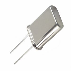
In PCBs, crystal oscillators act as programmable timers or clocks that periodically produce electronic signals. They’re so named because they depend on the resonance of a vibrating crystal—made of piezoelectric material—to dictate the frequency of the electronic signal or the oscillation.
Different piezoelectric materials can be used to create the resonance, but quartz crystals are by far a community favorite. The oscillator uses an electric field in tandem with the voltage applied to an electrode near the quartz crystal to create a property known as inverse piezoelectricity. The electric field is then removed to allow the crystal to return to its previous shape. As it does this, the quartz generates another electric field that, in turn, generates a voltage at a specific frequency—in other words, the oscillation.
Crystal oscillators are usually used as precise timers for wristwatches, microcontrollers, and other similar gadgets.
Inductors – Increase Energy
Inductors, like resistors and capacitors, are considered linear passive components of PCBs. Like capacitors, inductors are two-terminal devices that store energy. But whereas capacitors store energy electrostatically, inductors use a magnetic field.
Also known as coils, chokers, and reactors, inductors typically consist of a core wrapped with insulated wire. The more times the wire is wrapped around the core (i.e., the number of windings), the greater the magnetic field—and therefore energy—is generated. The windings amplify the magnetic field and, by extension, the stored energy, and energy capability of the device.
Inductors are characterized by a property called inductance, which is basically the ratio of the voltage compared to the rate of change in the current. They’re often used to filter or block certain signals, such as radio interference in audio equipment.
Switches – Power Buttons
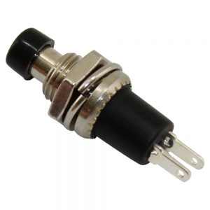
A switch is yet another widely known PCB component, second only to batteries. Lots of people—again, not just engineers and hobbyists—purchase switches for casual, everyday functions. They don’t just belong on printed circuit boards. They’re seen in kitchens, rooms, remote devices, etc.
Think of switches/relays as power buttons. They basically control the flow of the current in a circuit by opening and closing the circuit. One flick of the switch and the circuit opens, allowing the current to flow to the lightbulb in a room. Another flick and the circuit closes. The bulb is cut off from the current and powers down.
There are a dozen different types of switches at least, all varying in physical construction and appearance. The more common ones would be push-button switches, levers, and toggle switches. Other examples include box-type, rocker, micro, slide, and rotary switches.
Potentiometers – Varied Resistance
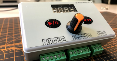
Potentiometers are basically variable resistors with three terminals. Like resistors, they control energy in the circuit. They’re so-called because they basically dictate the electric potential—or voltage—of a device. Common potentiometers come in two types: rotary and linear.
Rotary potentiometers are a little more well-known than linear types. They make use of a knob to vary the resistance of the device, allowing the slider contact to move over a semi-circular resistor to dictate how high or low the energy should be. The most popular example of a rotary potentiometer in play would be the volume control knob on the radios. The amount of current to the amplifier is controlled by the potentiometer, consequently controlling the audio volume.
Linear potentiometers are much the same, only it’s a straight line rather than a semi-circle. Think of the volume control buttons on modern smartphones or headphones.
SCR – High Current Control
SCR stands for Silicon-Controlled Rectifier. Like transistors and diodes, SCRs—also called thyristors—are so named because they’re made up of four silicon layers (instead of the three NPN or PNP compositions found in transistors). In some ways, they can be seen as two transistors working in tandem to control high amounts of voltage and power. In this sense, they’re a little more suited to high AC projects and operations where a regular transistor might not be enough.
The four layers—NPNP or PNPN—function more as switches rather than amplifiers. What’s more, it takes just one pulse to activate said switches rather than the consistent current found in single or bipolar transistors.
Sensors
And last, but certainly, not the least, we have sensors. They’re pretty straightforward electronic components in that they “sense” physical input or environmental changes and react accordingly. The type of input can range from changes in heat, light, and moisture to pressure, noise, motion, or more.
The response generated by the sensor comes in the form of an electrical signal corresponding to whatever type of change they’ve detected. This signal is then sent to other components in the circuit or PCB.
If programmed to, these sensors then generate an output in the form of human-readable displays or more signals transmitted electronically for future reading or further processing.
Printed circuit board sensors typically convert physical energy to electrical energy. In a way, this makes them converters. Sensors are actually quite flexible and can come in many forms. They can even come as diodes like the red LED light on a television remote that signals whether the device is on or off. Common practical implementations of sensors include humidity measurement, air quality detection, motion sensors, and automated lights.
Conclusion
To recap here are the 13 most common PCB components we covered:
- Resistors
- Capacitors
- Transformers
- Transistors
- Diodes
- Batteries
- Integrated Circuits
- Oscillators
- Inductors
- Switches/Relays
- Potentiometers
- SCR
- Sensors
If you’re a beginner and a hobbyist, these 13 electronic components will prove fairly easy—and useful—to work with when you dive into creating your first few PCBs. Even if you’re fairly experienced, it’s always good to get a grasp of the basic building blocks. These 13 electronic components all contribute to a PCBs functionality in their own way, and one isn’t more preferable than the other. The difference in their abilities and designs makes them suitable for different corresponding projects.