How to Use a Function Generator
This is how to use a function generator to test a circuit’s behavior:
- Power on the generator and select the desired output signal: square wave, sine wave or triangle wave.
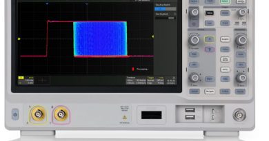
- Connect the output leads to an oscilloscope to visualize the output signal and set its parameters using the amplitude and frequency controls.
- Attach the output leads of the function generator to the input of the circuit you wish to test.
- Attach the output of your circuit to a meter or oscilloscope to visualize the resulting change in signal.
A function generator, which is used for testing the response of circuits to commonplace input signals, produces various voltage patterns at different frequencies and amplitudes. You connect the function generator’s electrical leads to the ground and the signal input terminals to the device under test (DUT).
The majority of function generators enable you to pick the shape of the output from several options including square wave, in which the signal immediately goes from high to low voltage; sine wave, in which the signal curves from high to low voltage like a sinusoid; and triangle wave, in which the signal goes from high to low voltage at a fixed rate.
Advanced function generators — known as arbitrary waveform generators — use direct digital synthesis techniques to generate any waveform that can be described by a table of amplitudes. Some arbitrary waveform generators can also operate like an ordinary function generators and often include waveforms like square, sine, ramp, triangle, noise, and pulse as well as waveforms such as exponential rise and fall time, sinx/x, and cardiac.
The function generator’s amplitude control changes the voltage difference between the output signal’s high and low voltage. Its direct current (DC) offset control changes the signal’s average voltage with regard to the ground. The function generator’s duty cycle is its ratio of high to low voltage time as it concerns square wave signals.
The function generator’s frequency control is used to manipulate the output signal’s rate of oscillation. On certain function generators the frequency control combines several different controls: one set of controls sets the frequency range, or order of magnitude, while the other selects the exact frequency. This enables the function generator to handle the dramatic variation in frequency scale required for signals.
You use a function generator by powering it on and configuring the output signal to your intended shape. This entails connecting the ground and signal leads to your oscilloscope to check the controls. Then you adjust the function generator until you get the appropriate signal and attach the function generator’s ground and signal leads to the device under test’s input and ground terminals. While attaching to ground will typically suffice, in some situations you may need to attach the function generator’s negative lead to the device’s negative input.