DIY Function Generator: From Prototype to Creation
Looking to create your own function generator? You’ve come to the right place! In a previous article, we walked through how to make a function generator on the powered PBB-272C powered breadboard. Now, we’re going to explain how to take a waveform generator prototype to your own DIY function generator!
Why Build a Function Generator?
Beyond saving money (function generators can be expensive!), a DIY function generator is a fantastic way to learn how to take a prototype to a final product.
You might walk away with a greater appreciation for this important test equipment. But ultimately, you’ll come away with a brand new function generator that you can use to test your next prototypes and electronic projects!
How to Build a Function Generator
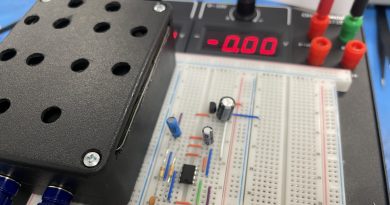
In part one of this series, How to Build a Function Generator on the PBB-272C Powered Breadboard, we prototyped and tested the circuits for a function generator. If you haven’t completed this step yet, we highly recommend checking out that article.
With a completed prototype, the next stage of development is Printed Circuit Board (PCB) production. There are a couple of techniques that could be used to fabricate a PCB:
- Perf board—The easiest way that you can recreate the circuit is on a perf board. To learn more about how to make a perf board, you can read this article here “Mother’s Day Gift Circuit Specialists’ Style”
- Etching Copper Board—Another way to bring your design to life is the Etching Copper Board technique where a negative will be transferred onto a copper board. Then you’ll soak the copper board in a chemical solution to etch the design onto the copper board. We have everything to start etching your own design using the ET20 etching tank and Fab-In-A-Box kit.
- Third-party Service—Finally, the most efficient way to make a PCB is to send the design to a PCB fabricating service provider. This will make sure that the PCB quality is consistent throughout. This will be the most economical method especially if this item will be for sale.
For this tutorial, you’ll get an inside look into how a third-party service fabricates a PCB. With the right equipment, you can do this yourself!
Parts Needed
- Function Generator DIY Soldering kit
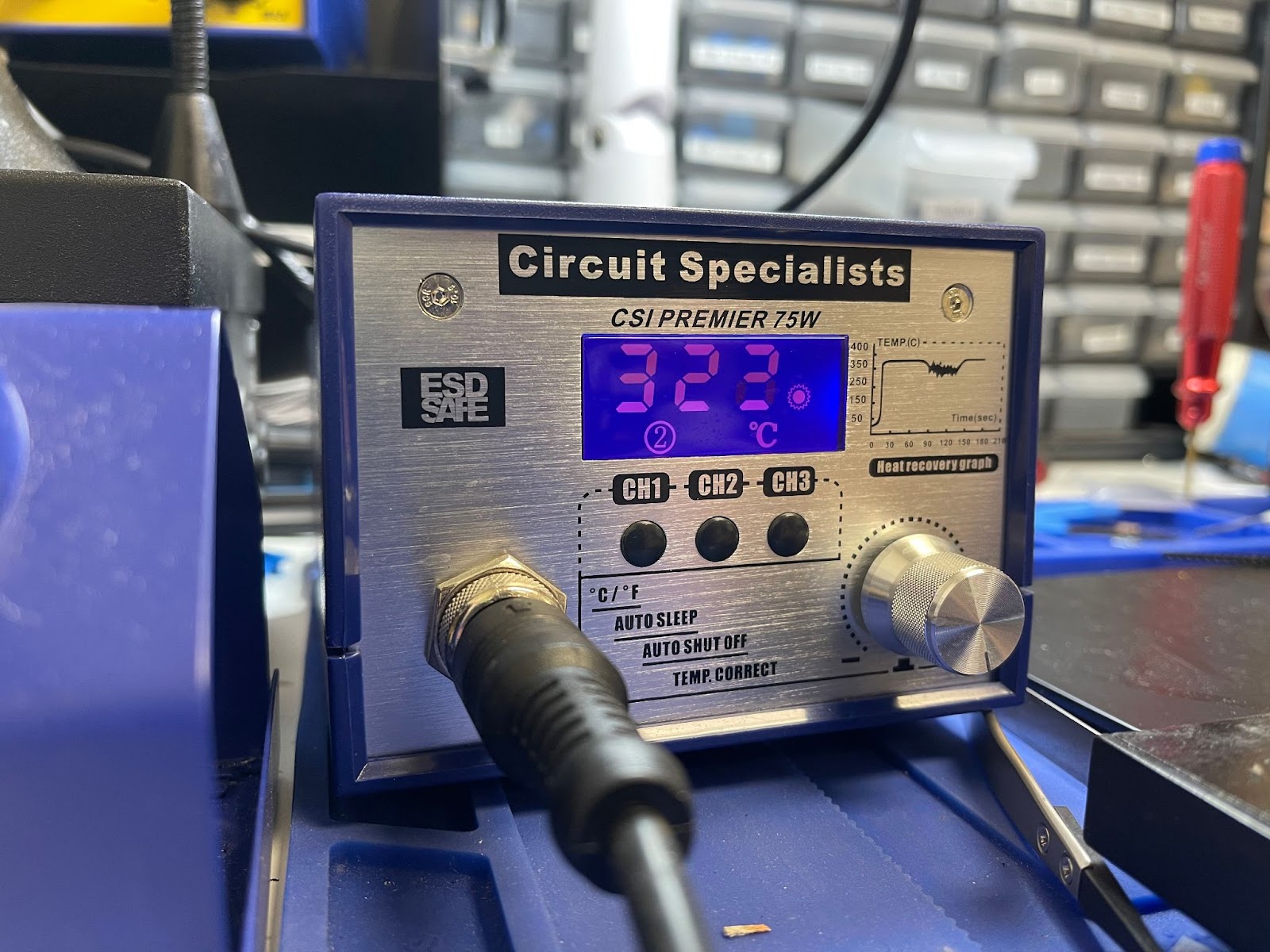
- Soldering Station 75D or Station 75 Premiere
- MG Chemicals 4894 Solder Wire
- MG Chemicals 8341 Flux Paste
- Tweezer set
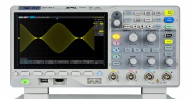
- Handheld Oscilloscope 2D72 (for testing)
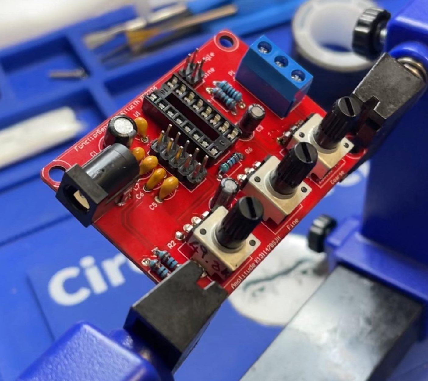
Instruction on How to Solder
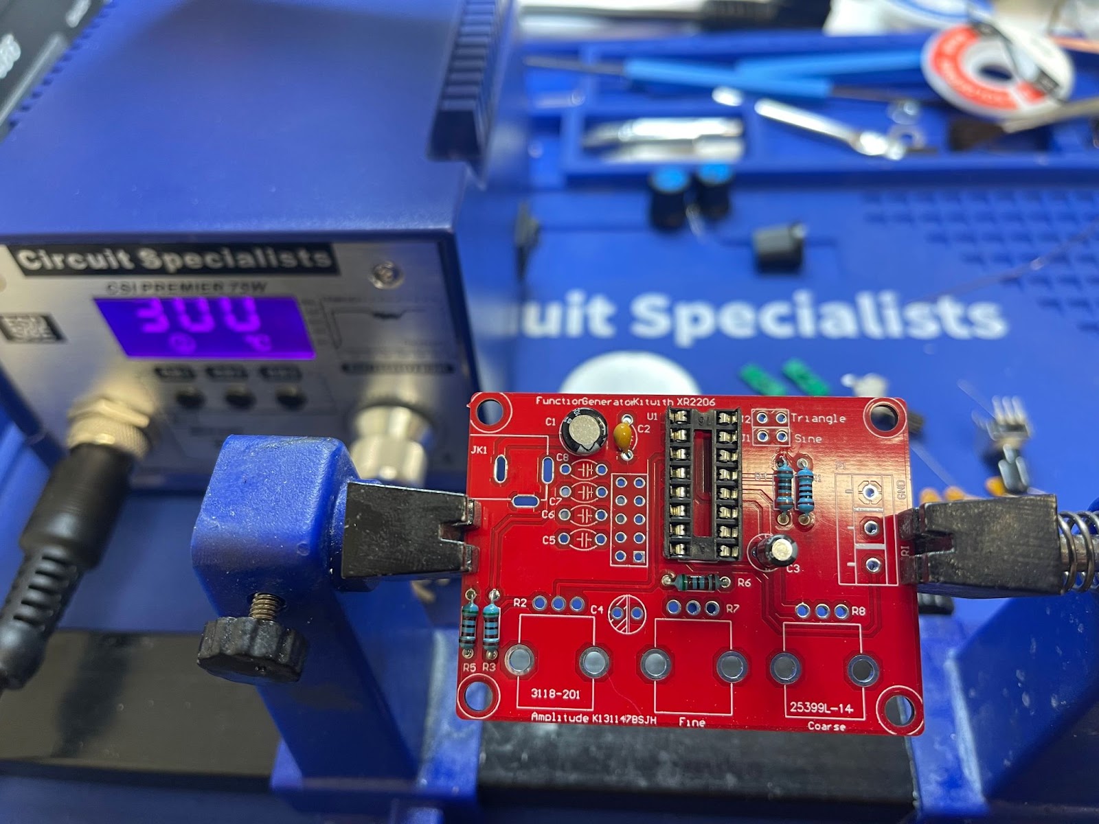
- Soldering IC Socket onto the PCB.
- Set the CSI Premiere 75 soldering station at 300 degrees F and solder all small components such as resistors, capacitors, etc.
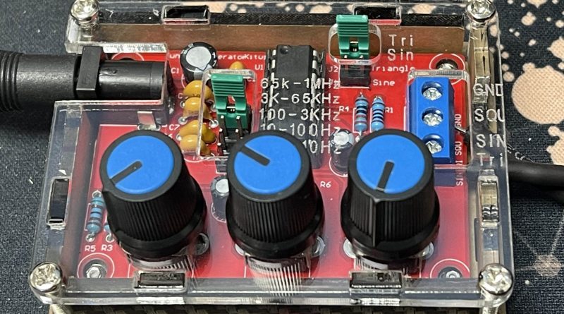
3. Next, solder the header pins to the PCB. These header pins play a big role in what type of waveform and the range of the frequency the unit will generate
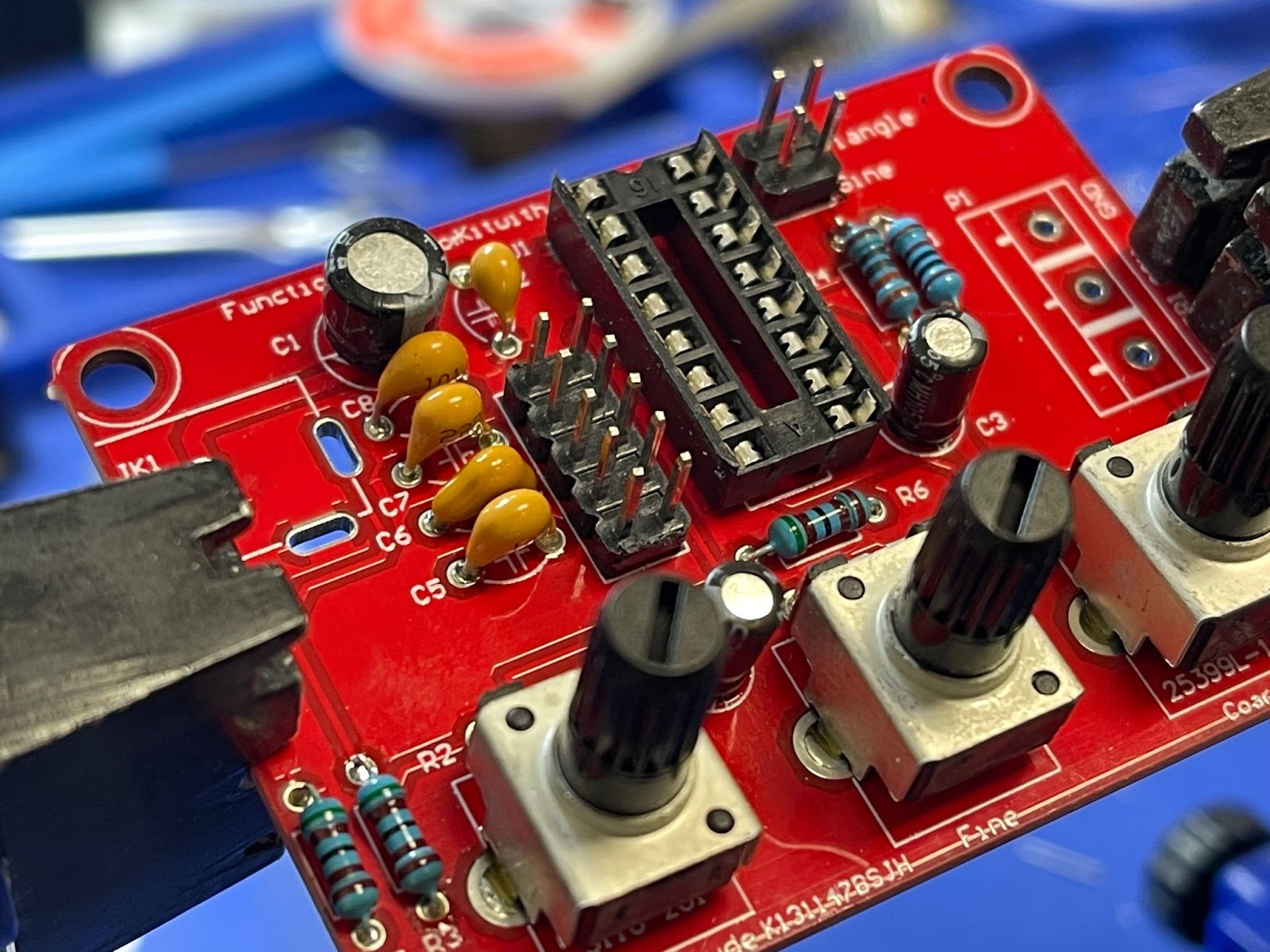
4. Solder potentiometers to the correct designated area on the PCB (this is crucial).
- Finally, solder the power connector and terminal block to the PCB and complete the assembly process.
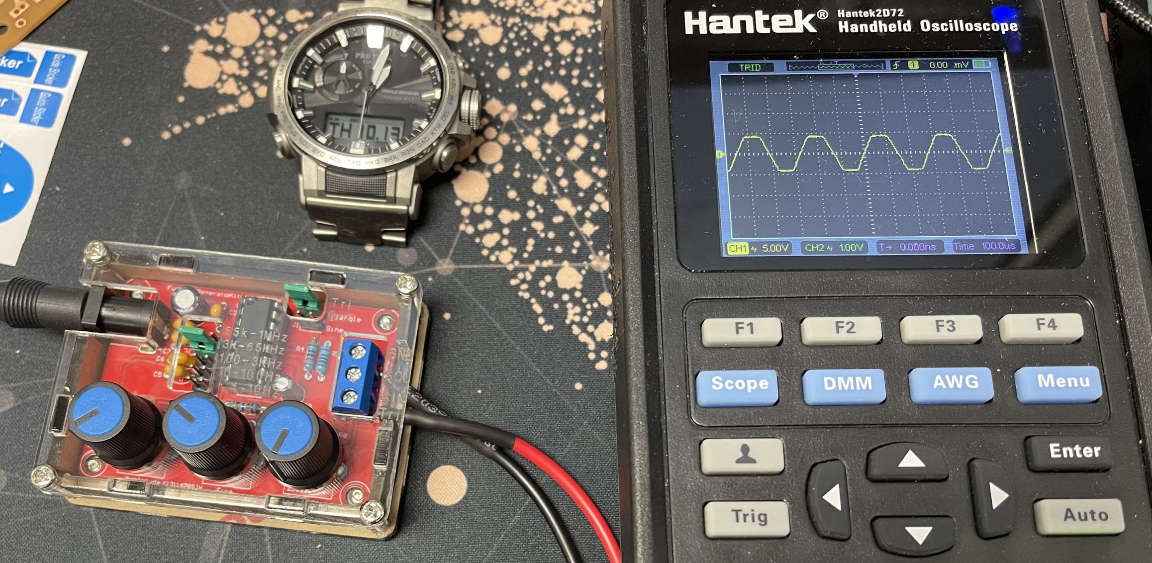
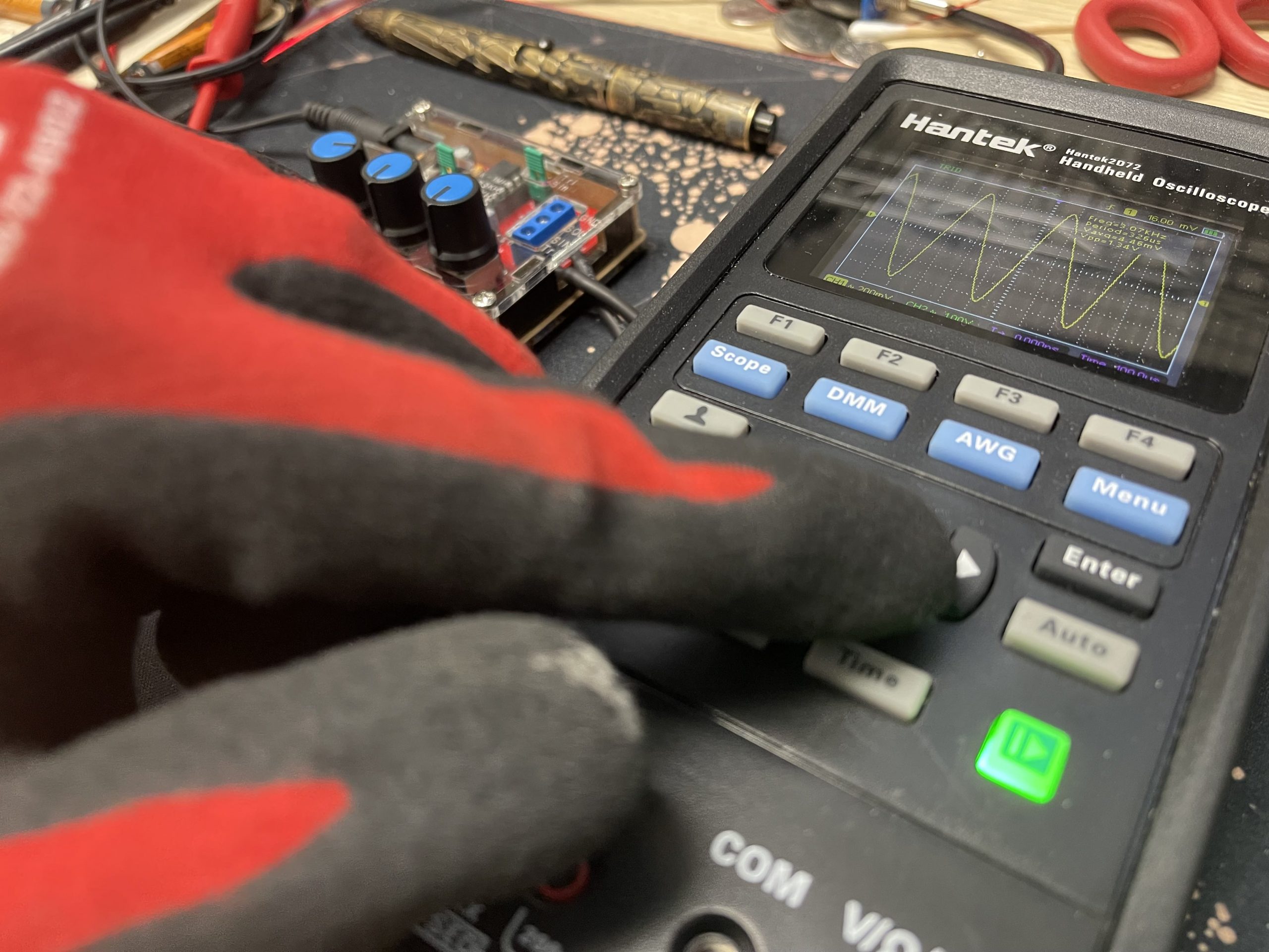
How to Test the DIY Function Generator Circuit
- Firstly, supply the Waveform generator with a 9V 1A power source and connect the probe to the correct waveform terminals.
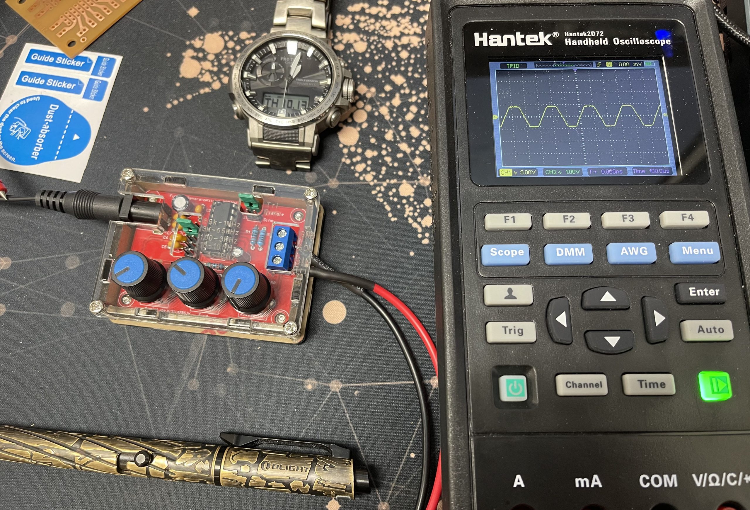
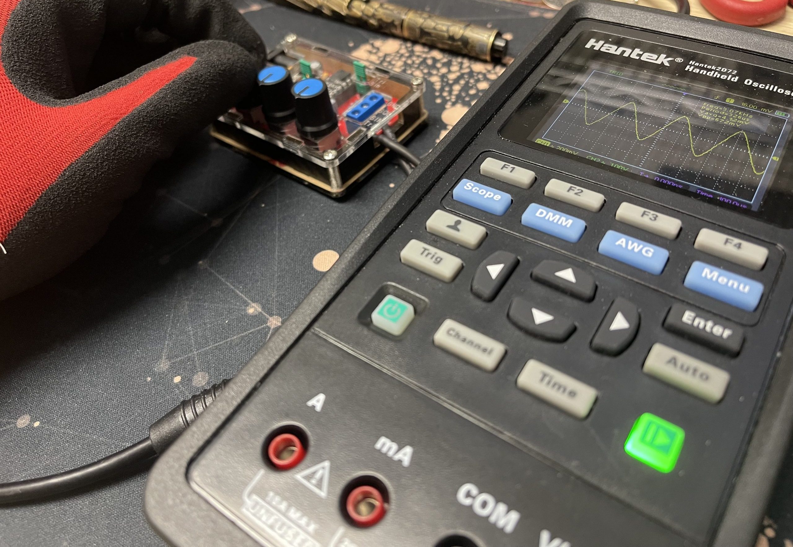
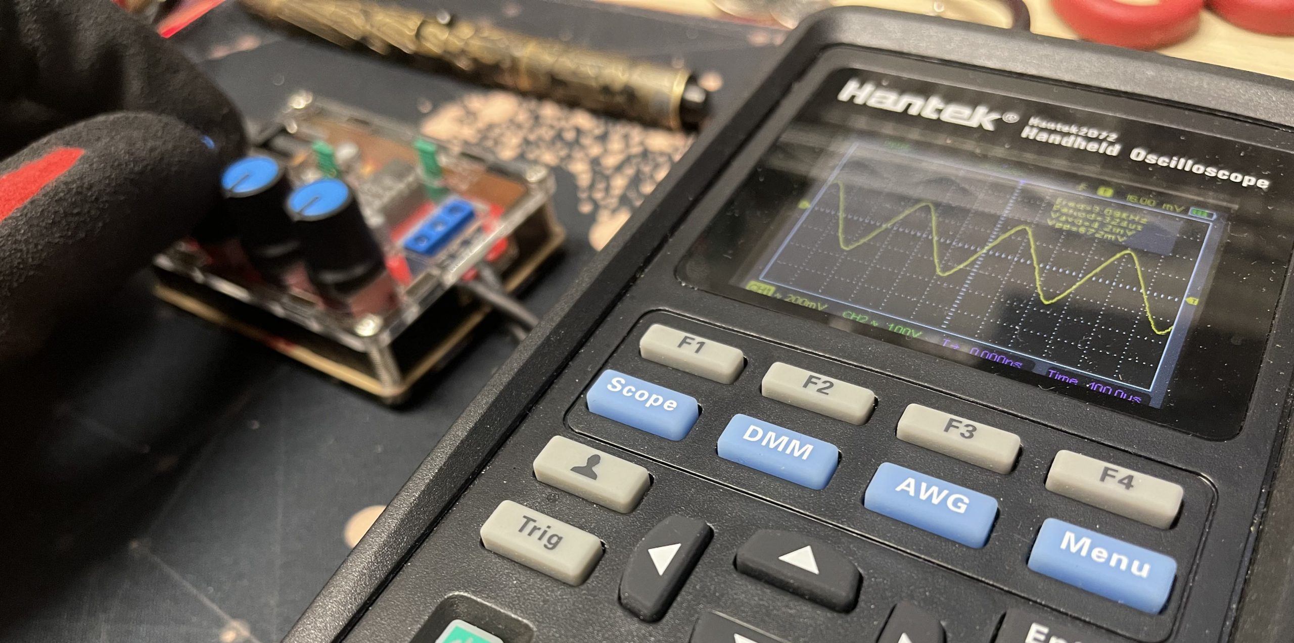
- Next, use the knobs to dial into the desired frequency and peak to peak.
3. In addition, the Hantek 2D72 has an auto set-up ability that with just one simple press the oscilloscope would pick the readable range for the input signal.
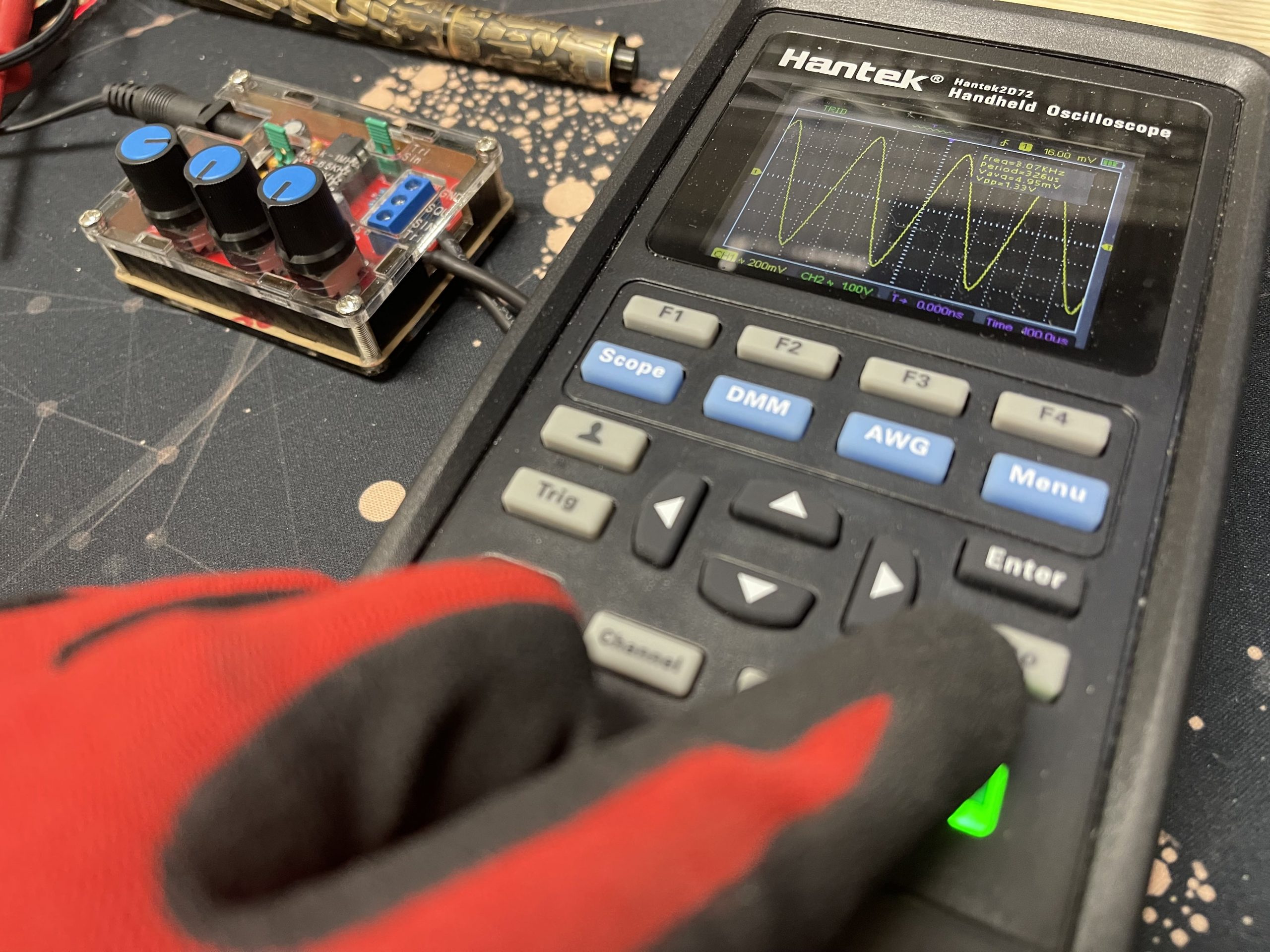
4. Furthermore, you can also use the Trigger button to manually trigger the waveform.
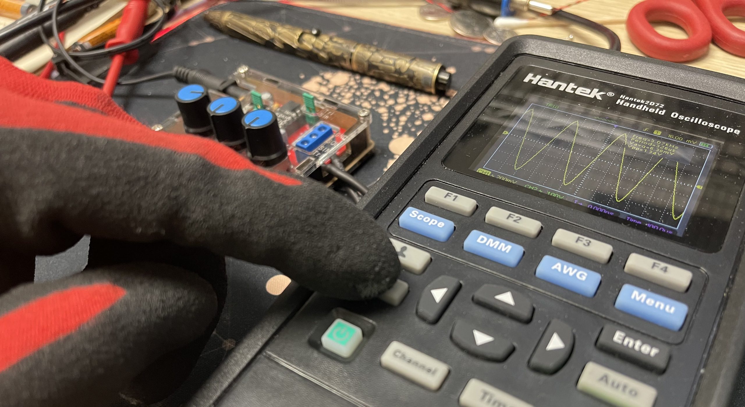
5. Finally you can you the right arrow to change the time base.
Conclusion
Once you’ve soldered your function generator together and tested the circuits, you’re ready to go! The last and final step: Use your function generator! For more electronics project ideas, check out our STEM education kits page. https://www.circuitspecialists.com/stem-education-kits
Comment below or email us at sales@circuitspecialists.com to tell us how it went.