Oscilloscope Probe Compensation Adjustment
All passive oscilloscope probes must be properly compensated to produce accurate waveform monitoring. This is required for both analog scopes and Digital Storage Oscilloscopes (DSOs).
Compensation is required to properly match the input impedance of the oscilloscope’s vertical input channel circuitry. This input impedance is typically 1 Meg ohm shunted by a small capacitance. The oscilloscope probe contains a variable capacitor that is used to “tune” the probes cable and distributed capacitance to match the input impedance of the scope.
Failure to properly adjust this capacitor could result in distorted waveforms and incorrect measurement values. Most oscilloscopes contain a compensation output signal that makes probe compensation simple without requiring any additional equipment. The Probe is connected to either one of the input channels of the oscilloscope and the probe tip is then connected to the compensation signal. The compensation capacitor on the scope probe is then adjusted, using a non-metalic adjusting wand, to display a waveform with sharp edges. Any peaks or rounding of the waveform display indicate an improperly compensated probe.
The following waveforms illustrate properly and improperly adjusted oscilloscope probe compensation.
| The waveform below is undercompensated. |
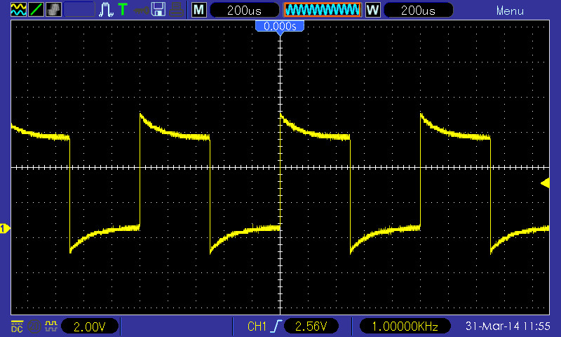 |
| The waveform above is overcompensated. |
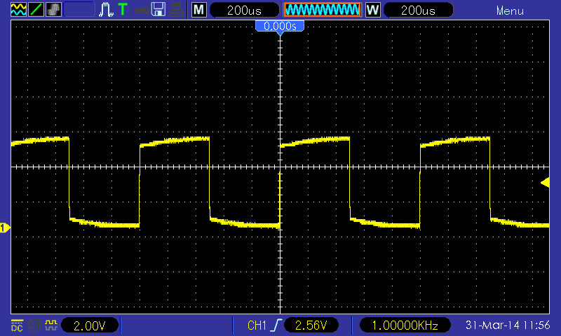 |
| The waveform above is properly compensated. |
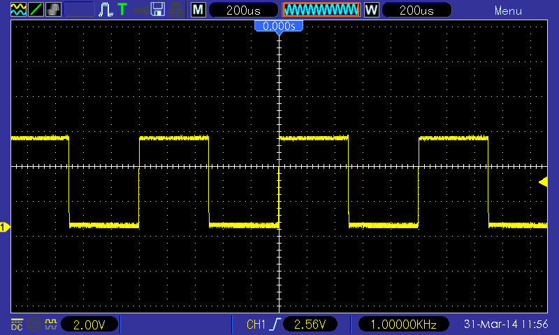 |