How to Build a Circuit On a Breadboard
Building a circuit on a breadboard is a great way to test prototype circuit designs. Here are the basic steps, if you want to know more about how to build a circuit on a breadboard, see the detailed explanation below.
- To connect circuits or components on your breadboard you will need jumpers – small pieces of 22ga solid core wire.
- If your breadboard is unpowered, you will need power cables with banana plug on either end.
- Start your project by mounting any integrated circuits by inserting them carefully into the IC section of your board, taking care to make sure they straddle slots in the board, isolating each of the circuit’s pins.
- Add other components to open spaces on the breadboard, wiring them with jumper wires as you go.
- If you run out of space in a column, you can use jumper wire to connect an unused column with open sockets.
- Once your circuit is complete, connect the power wires and the outputs of your circuit.
Whether you’re an electronics hobbyist, student, or technician you will sometimes want to build a temporary circuit with breadboard, which is a flat set of small sockets arranged in columns and rows built into a stable and non-conductive base, enabling you to quickly test circuit design without breaking out your soldering iron. Because the points in each column are already wired to one another, any leads or wires inserted into them become electrically connected. Adjacent columns on the breadboard are insulated from one another.
The breadboard is divided into a main area in which you build your circuit surrounded by a smaller power bus section with the buses organized in horizontal rows. There are also horizontal slots in the main section designed for integrated circuits. Cut pieces of twenty-two gauge solid insulated wire into at least thirty jumper wires of lengths between two and ten inches, stripping roughly half an inch of insulation from both ends of each jumper wire.
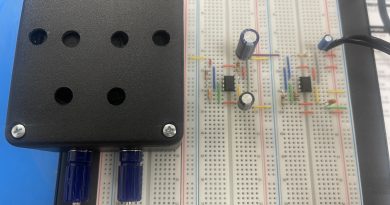
Make sure the adjustable DC power supply is off and then insert one end of a pair of banana cables in the positive (red) and ground (black) connectors of the breadboard and insert the other end of the banana cables in the appropriate banana binding post jacks. Place a three or four inch length of jumper wire in the small horizontal hole of each binding post, tighten both posts, and insert the other end of each wire in a separate power bus row.
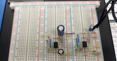
If you have integrated circuits, insert them into the breadboard, using just enough pressure to secure them while ensuring none of the integrated circuit’s pins bend. You want to position the integrated circuits so the key tab or dot points to the left. The integrated circuits should straddle slots in the plastic of the breadboard, which electrically isolates each of the integrated circuit’s pins.
Insert the other components into the breadboard holes while observing the row-column connection scheme. If you run out of holes in a column simply insert a jumper wire between that column and an unused column for additional connections. After that use jumper wires to connect the power bus holes and sections of the circuit requiring DC power and ground. If the circuit has outputs, insert lengthier jumper wires in the outputs and connect them to the appropriate external equipment.
Double-check all the connections on the breadboard, correcting any misplaced components or wires. Set the current and voltage of the power supply to match your circuit design and then turn it on and test the circuit. If you need to make additional changes be sure to turn the power supply off, make the changes, and turn it on again.