Troubleshoot an Audio Amplifier with an Oscilloscope
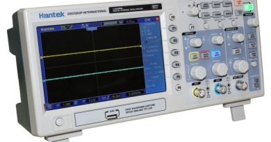
An oscilloscope can display the shape of an input signal wave, enabling you to observe waves and test electrical currents. You can use an oscilloscope to test your audio amplifier for blown fuses, improper biasing, signal distortion, and other sources of poor sound fidelity. Older style oscilloscopes display the wave on a cathode ray screen whereas a digital storage oscilloscope features a digital screen. The wave’s shape will enable you to better understand the performance of your audio amplifier. A smoother wave typically represents a better sound.
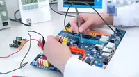
Remove the back and top panels of the amplifier with a small screwdriver and place the screws on a strip of electrical tape in the order you remove them, so that later on you can find the right screws faster and easier. After you remove the panels you will see the circuit board and chassis ground.
Connect a sine wave generator or a function generator to the amplifier’s input. Depending on the type of test you are conducting, you may not need a generator (for example, you won’t need one to test the voltage of the circuit board). However, it’s simpler to have an unused generator connected to the amplifier rather than frequently connecting and disconnecting one.
Take the red cable from an electronic load and connect it to the amplifier’s output socket. The electronic load receives attenuated power, simulating ordinary operation without the amplifier processing the signal. While testing the amplifier needs to function as it normally would, but if you have speakers connected you can damage them as well as your hearing. The current has to go someplace, so the electronic load absorbs it, protecting the amplifier’s output stage while testing.
Clip the ground cable of the oscilloscope to the amplifier’s chassis ground, which is usually a bolt mounted on the side or the back of the inside of the chassis, and turn on the sine wave or function generator. Set all controls on the oscilloscope to zero and set the oscilloscope to direct current coupling.
Turn on the audio amplifier. Be careful you do not accidentally disconnect the ground cable while testing. If the ground cable is disconnected you risk electrocution.
Press the oscilloscope probe to the part of the amplifier you would like to test — for example, the output transformer — and hold it securely to keep it from slipping away from the amplifier. Adjust the oscilloscope’s time and volts dials to adjust the view on the oscilloscope grid. The horizontal axis displays the time, the vertical axis displays the voltage, and the resulting curve shows the how power dissipates as it flows through the amplifier.
Observe the oscilloscope grid as you move the probe to different parts of the amplifier. If you notice uneven waveforms with inconsistent peaks, you may have an issue in that part of the amplifier. Components with a regular ripple-like waveform are usually fine.
Turn off the sine wave or function generator and switch the oscilloscope to AC coupling so you can test the power supply. Press the oscilloscope probe to the power transformer. If the waveform does not ripple a primary winding may be shorted or about to short.