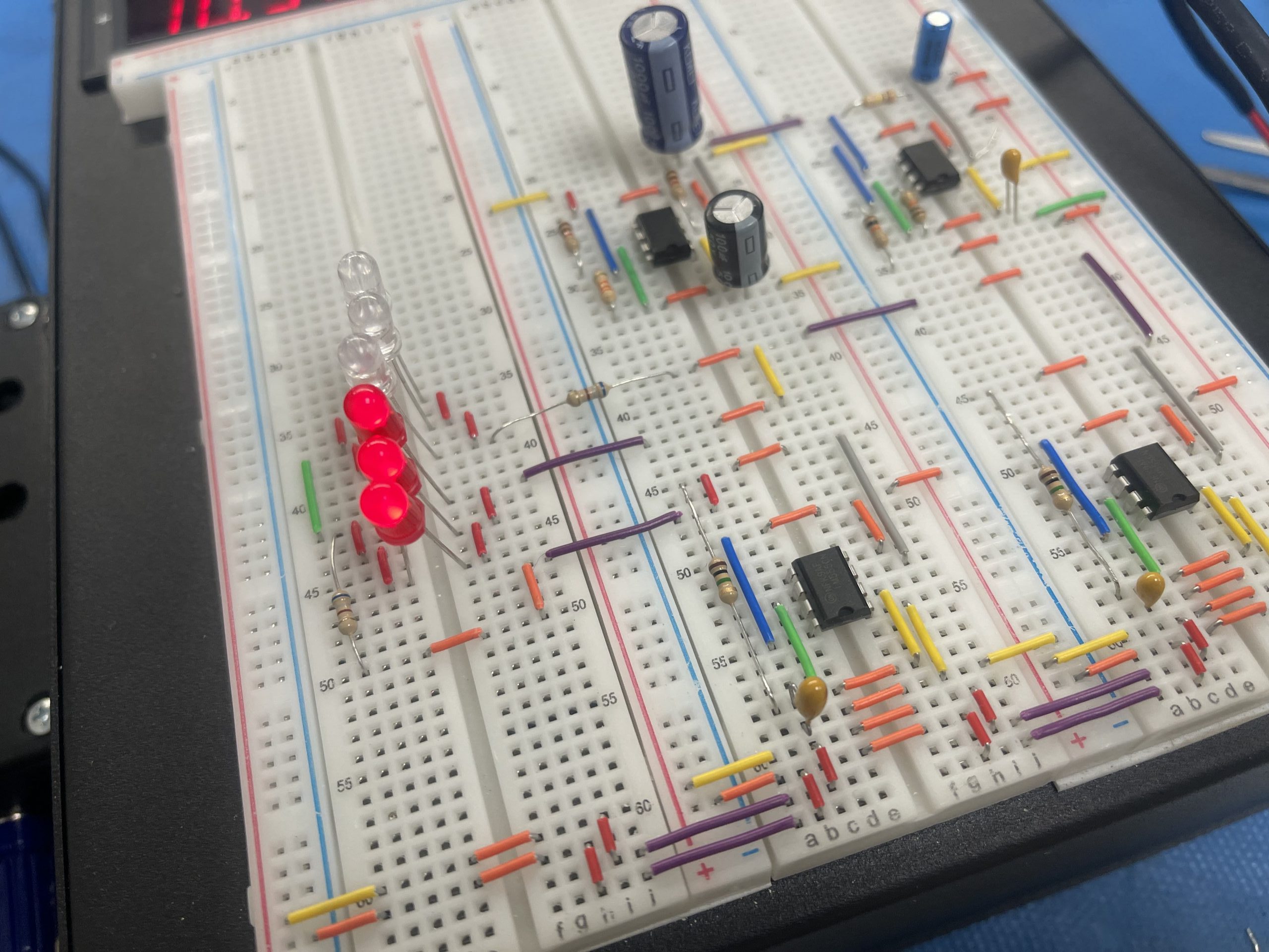
Build Police LED Flashing Circuit on Power Breadboard PBB-272B
A tutorial on how to make a Police LED Flashing Circuit on Power Breadboard PBB-272B. We are going to use 2 famous 555 timers to control the pattern of the flash by the capacitors. For instance, this circuit alternatively flashes between Red LEDs and Blue LEDs. While blinking each of them individually similar to police strobe lights. We also integrate the last project Police Siren Circuit on Power Breadboard PBB-272B to this so we have a complete sound and light system.
Table of Content
- Part List
- Circuit diagram
- How the Circuit Works
- Conclusion
Part List
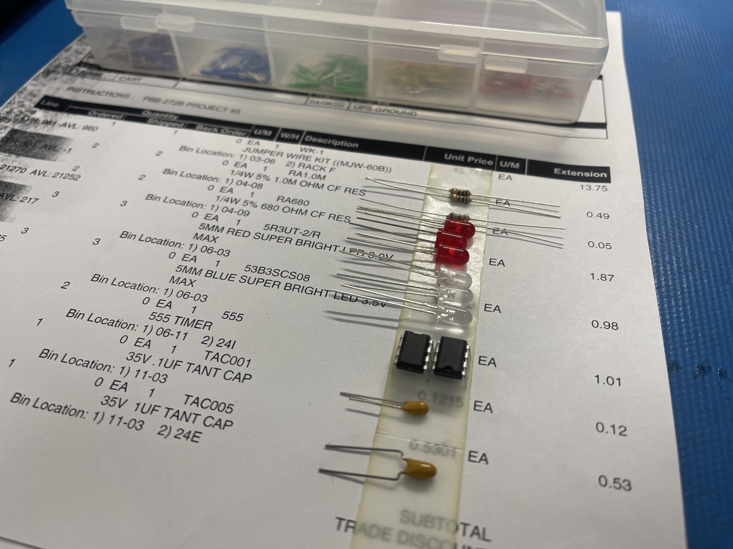
- 2 x 555 Timer
- LED’s: 3 x Red, 3 x Blue
- Resistors: 2 x 1M, 2 x 68Ohm
- Capacitors: 1uF, 100nF
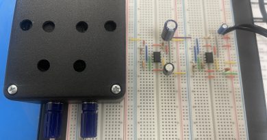
- Power Breadboard PBB-272B
- Jumper Wire
Note: Depending on the power supply used and the way LEDs have connected, either series or parallel. You need to use a different resistor than 68R used in series with the LED. You can read this article 5 Steps to Calculate the Resistor value for LEDs to learn more.
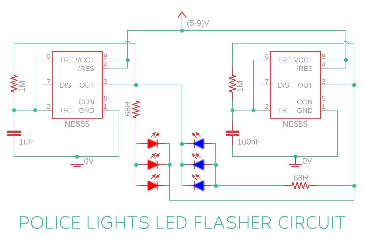
Circuit Diagram
How This Circuit Works
First, we learned how to configure 555 timer IC to operate in astable mode. We also connected 2 LED’s in opposite polarity at the output so that they toggle ON and OFF at regular intervals of time.
In this police strobe lights style flashing LED circuit, we have used two copies of similar astable circuits configured at different frequencies. The first 555 timer IC, uses a bigger capacitor and so it takes more time to toggle the output. The second 555 timer IC uses a smaller capacitor and so it toggles the output very fast.
Now coming to the arrangement of LEDs, The first LED group (Red LEDs) turns ON when there is a positive voltage at the anode and a negative voltage at the cathode. This scenario happens when the output of the first 555 timers IC is ON and the output of the second 555 timer IC is OFF at the same time.
Similarly, the second group of LEDs (Blue LEDs) turns ON only if the output of the first 555 timers IC is OFF and the output of the second 555 timer IC is ON.
So when the output of the first 555 timers IC is ON, only the first group of LEDs have a chance of turning ON and they blink at the speed with which the second 555 timer IC toggles the output.
Similarly, when the first 555 timer IC turns OFF, only the second group of LEDs have a chance of turning ON and they blink at the speed with which the second 555 time IC toggles the output.
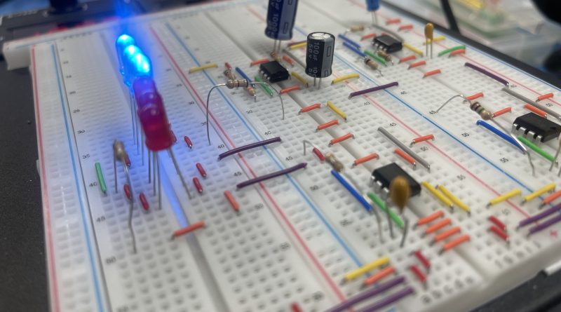
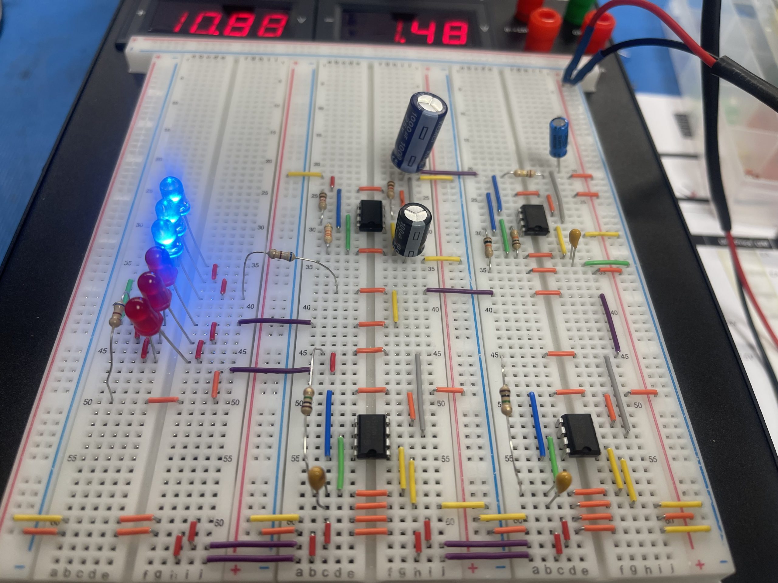
Repetition of this cycle, again and again, creates this cool LED flasher effect similar to flashing lights used on police cars.
Conclusion
Working Video: https://youtube.com/shorts/l_hPXDyYJVI
We hope that this tutorial on how to make a Police LED Flashing Circuit helps you understand the 555 and its applications. This project integrates the last project to this so we have a complete sound and light system. We will use this knowledge next time to bring something from a prototype to a complete product.