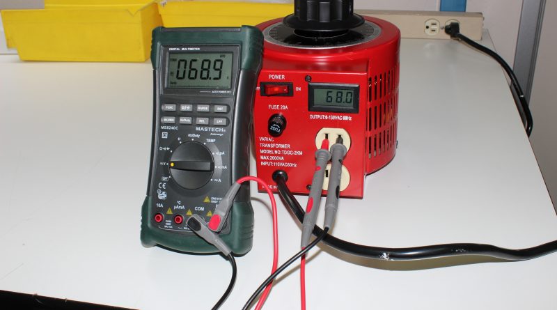
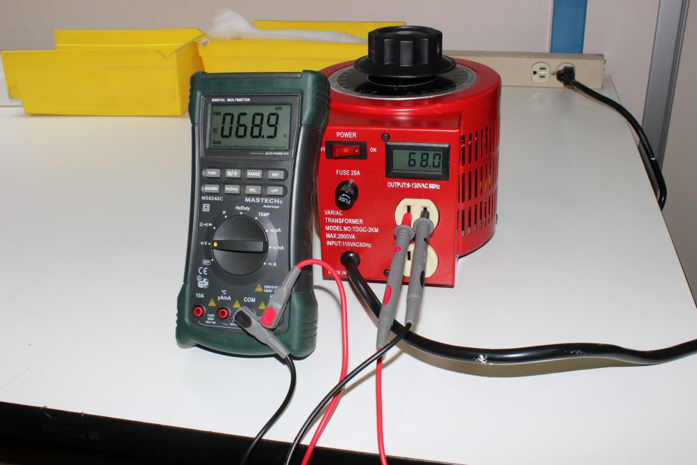
Monitoring Variac Output with a Digital Panel Meter (DPM) [tutorial]
While most users are not concerned about the absolute readout of variac output voltage, a more accurate digital meter may be desirable.
Over the years, Circuit Specialists has offered several different sizes of Variacs. These variable autotransformers have proven to be not only reliable, but can make a huge difference when it come to protecting your electronics. The only reoccurring complaint we’ve received on these units has been based around the accuracy of the built in analog variac output meter.
This application note will describe a simple retrofit of a digital panel meter to replace the stock analog meter.
The PM628 digital panel meter was chosen due to its low-cost, ease of interfacing, and small size. This particular meter is almost identical in size and shape to the analog meter supplied with the Variac.
The PM628, like all generic DPMs, has a 200 mV full scale reading, so the appropriate scaling resistors are required to display RMS voltage of the AC power. In addition to the voltage divider resistors, a simple half wave bridge rectifier must be added to convert the AC voltage into DC which can be read by the DPM.
A low cost 1N4004 rectifier diode was inserted in series with the AC voltage and the voltage divider resistors.
Since the DPM contains electronic circuitry, it requires a source of DC power for its operation. A wide range of options exist so it was easy to find a suitable AC/DC converter module that would power the DPM and not take up too much space in the Variac enclosure.
The calculation of the scaling resistors was a little more complex than applications for a DC source because the ½ wave rectified output from our single diode produces a rectified equivalent DC voltage equal to the average value; which is 0.45 times rms voltage.
For 120 VAC this works out to 120 X .45= 54 volts. Since we want the readings in RMS we have to calculate the voltage divider to produce 120 mV with 54 volts applied., Therefore for 120 volt RMS the peak value is 1.414 X RMS or approximately 170 volts. So we will set the voltage dividers to present 120 millivolts to the meter with 54 volts at the input.
I opted for a 1K shunt resistor and calculated the required series value.
.120=54(1k/(1K + Rseries) ) or 1K + Rseries=54K/.12
so Rseries=450K-1k=449K
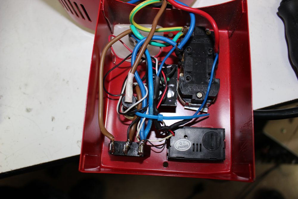
So a 449K resistor and a 1N4004 rectifier diode were placed in series with the input lead to the meter and a 1K resistor connected across the meter input. 430K and 18K resistors were connected in series with the meter to come as close as possible to the calculated value. Note that the voltage value displayed on the meter can be fine-tuned by adjusting the trimmer potentiometer on the back of the DPM.
The relatively small size and low cost of the required components makes this an easy voltage output upgrade to any of the Circuit Specialists Variacs.
Keep updated with all of our hacks, mods, and electronics tutorials by subscribing to our newsletter, facebook, and twitter!
Click here for a PDF file with a schematic for the panel meter retrofit
Until next time,
Circuit Specialists
Tempe, Arizona
480-464-2485
![]()

Great Post! Thanks for doing the work on this as it really needs a better meter to prevent over-voltage. I wish the transformers did not exceed 120VAC. The stock meter is useless. It would be really nice if a complete kit with schematic/instructions were sold by CS. I have to track down the parts and ask about the schematic, which doesn’t look quite right. The way the schematic reads (according to the meter spec) 120VAC is applied to the meter signal input (smoke?) and the conversion/scaling circuit discussed in the article is connected to the 5VDC power input. Should the schematic read: the scaling circuit on white/fine black wire meter signal input, and a 5VDC PS between 120VAC and Red/larger black wire?
Thx!
Also, I don’t see any convenient AC/DC converter 5V module online. Any small PS with 120V input is usually going to have an AC plug on it. The link shows a chip which might be beyond a lot of people to design and put together. The photo looks like it has a small epoxy filled box, if that is the module. If I can’t find anything, I would probably repackage a 5V AC adapter.
Thx!
I am a beginner hobby person. I would like to change the analog meter as you describe.
Looking at the schematic, I do not see where you use an AC/DC convertor.
Is there a more clear picture of the actual wiring? The wires in the photo are jumbled.
Is there a more stretched out view that would make the conversion easier to follow?
A schematic has been added to the post.