Portable Arduino Bot
Over the years, I have built many robotic projects and the Portable Arduino Bot is my favorite. During the programming phase of a project, I want to test out a new algorithm whenever I have some free time. Especially, during a lunch break but I do not want to carry the project around due to inconvenience. So that I can test my new code to see how it works in the real world.
There are many files available on Thingiverse for Arduino cases. However, I want to elaborate on a couple of LEDs and switch to the enclosure so might as well design one.
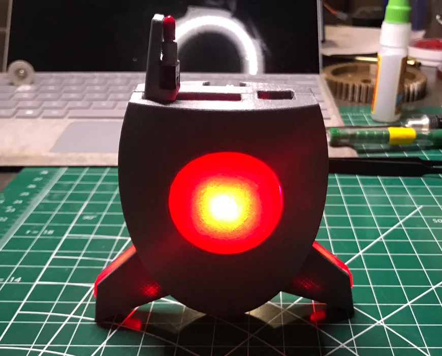
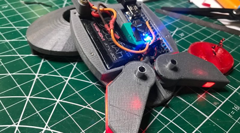
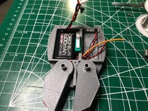
With that goal in mind, the Portable Arduino Bot was born. This Bot is small, compact, durable, and fully equipped with LEDs, switches, buzzers, etc. You can also equip the Bot with a sensor that could work with your project as well. I also wanted to encourage kids to program at a young age just like a new langue. And, what is a better way to do so by infusing the project with a Star Wars theme.
Table of Content
- What is an Arduino
- Parts List
- Assemble Proccess
- Coding and Testing
- What Next?
What is an Arduino
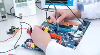
So let me explain a little bit about this amazing technology. The Arduino is a microcontroller board, it has up to 14 digital input/output pins (of which 6 can be used as PWM outputs), and 6 analog inputs or more. This allows the Arduino to read the input from sensors in the real world in real-time and react accordingly (amazing).
Parts List

- Arduino Nano
- 600 mAh Venom Battery
- Circuit Specialists Microswitch
- Circuit Specialists On/Off switch
- 10K Ohm resistor
- 3 x Adafruit LED
- 6 x 2×4 hex screw
Assemble
A1: 3D Printing Portable Arduino Bot
To download the STL files for this project please visit my ThingInverse profile below https://www.thingiverse.com
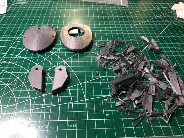
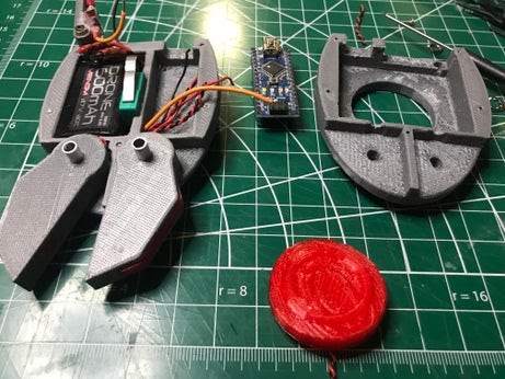
I will share the setup and the type of material that I used in this project. The usage of different materials may not gain the same result shown in the pictures. The Bot housing and the Bot’s legs should be printed with support. The support is only internal this will help the Bot to look better when it is completed.
I used a CEL Robox 3D printer to print all of the parts for this project. All parts are printed with 30% fill, CEL PETG HD Glass Designer Gray filament. And CEL PETG HD Glass Transparent Red filament was used.
A2: Microswitch
Microswitches have been around for many years, however, they have been in the spotlight recently. Now we can find these microswitches in 3D printers, robotic projects, vacuums, phones, etc. One might argue that you don’t need a switch for such a small project, however, I beg to differ. A switch can be used for many purposes. For instance, they can be used as a representation for a sensor in test simulations, or for an AI trainer. I will talk about the AI trainer later.
At first, when I read about microswitches, I thought it would operate just like a normal on/off switch, I was wrong, the microswitch requires a little bit of work and is not just a straight-up plug and play. If you are new to all of these, do not worry I was new too and if I can do it you can do it.
Note:
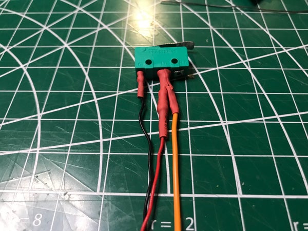
From my own experience, the confusing part is that the switch has 3 legs, we only use 2, but in the end, we will have 3 wires coming out from the switch. However, after much trial and error, I think I have it down, and I will make sure it is as straightforward as it can be. If you want to know more on how Micro Switches work, I found this website to be helpful http://www.me.umn.edu/courses/me2011/arduino/technotes/microswitch/
The switch has 3 pins: C, N0, NC. We only use C and N0.
A2.1. C for the ground wire
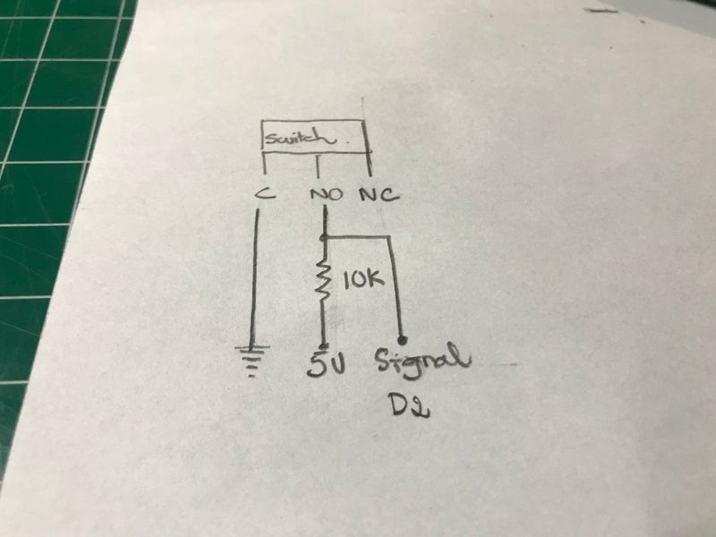
A2.2 Read this note before continuing: N0 will have 1 wire coming out from it, not 2. I have made this mistake many times and ended up with a bad signal. There is the main wire and a side wire, if you solder these 2 wires at N0, there will be a big chance that your signal will be unreadable or unstable.
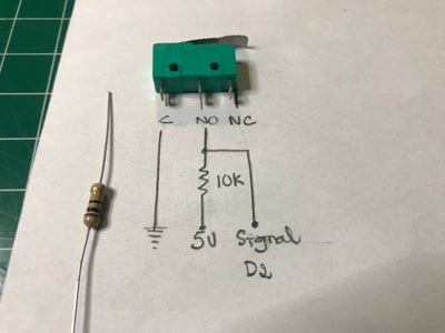
A2.3. The main wire will connect N0 to a 10K resistor, then after the 10K resistor will be the power source for the switch.
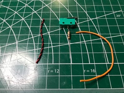
A2.4. The side wire will be connected to the main wire between the 10K resistor and N0. This is where we will collect our signal so that is why it is important to keep the data line clean.
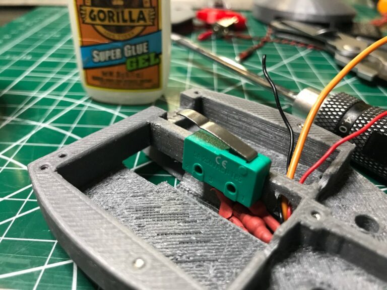
A2.5. Glue the microswitch in place and make sure to give it time to dry completely.
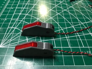
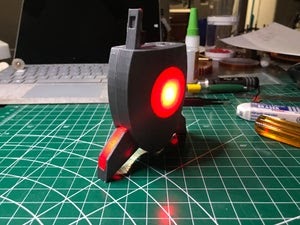
A3: Portable Arduino Bot Legs LED
This is the true power of 3D printing. The legs have an internal chamber for the wire and the LED. One of the challenges in the design is that the legs are movable. 3D printing technology provides me with a neat solution where I have an internal chamber for the wire to run through.
I used the Adafruit LED Sequins for their compact size and the resistor is included on the board for maximum space efficiency. All we have to do is solder a power and ground wire to the board. Heat wrapping the LED is optional, however, if you plan to have this project close to a running water source then heat wrapping is highly recommended.
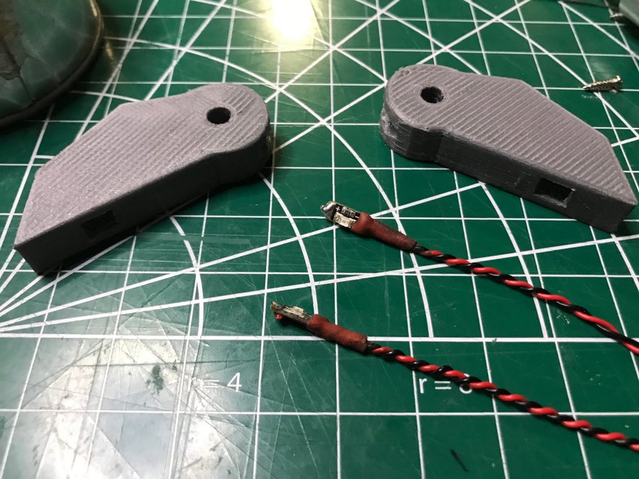
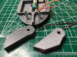
A3.1. Insert the LED into the leg

A3.2. Glue the LED down, make sure the LED is facing up for maximum illumination.

A3.3. Insert the Leg panel into each leg, this part is best to be printed with material that is transparent where light can travel easily.
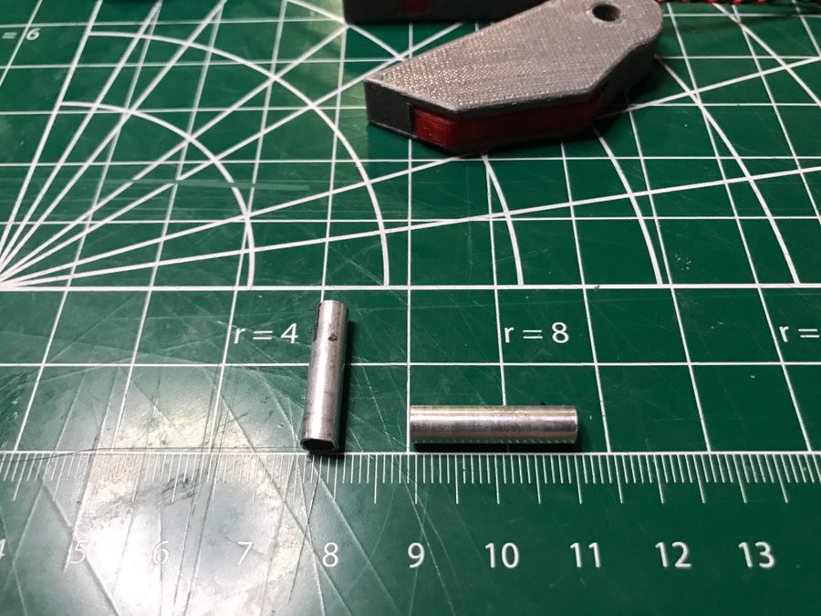
A4: Installing the Leg
I used 5mm aluminum tubes that I acquired from a local hobby shop. You can also 3D print these pegs or a wood peg would work just fine.
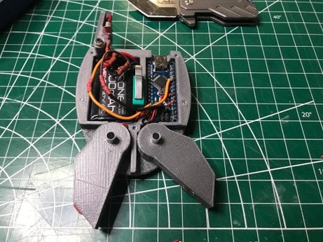
A4.1. Run the wires from each leg to the right section where it is going to house the Arduino Nano.
A4. 2. Make sure the legs move freely

A5: On/off Switch
The on/off switch is a lot simpler than the microswitch. This type of switch acts as a water gate, we just have to connect the switch to the circuit in series with the battery. The switch will then glue to the flip door.

A5.1.Make sure you give it enough wire so that the flip-door can be opened and closed.
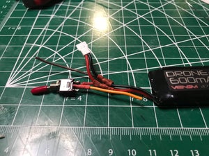
A5.2. Fit the battery in the housing.
A5.3. Get ready to solder all connections to the Arduino Nano.
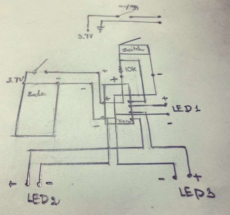
A5.4 Final wiring
A5.5. Double check the schematic
Coding and Testing
I would recommend uploading the PA_Calibration code onto the Bot to test out the legs LED. This will make sure that we assign the correct pin number for the correct LED.
 int ChestLED = 3 ;
 int LLegLED  = 2 ;
 int RLegLED  = 4 ;
 int LED_INDEX[3]={3,2,4}; // Chest LED, Left Leg LED, Right Leg LED
The calibration code will blink the legs LED and chest LED, to test to make sure the pins are not switched, you can change HIGH to LOW to turn off the LED to double-check.
 void loop()
 {
  digitalWrite(LED_INDEX[1], HIGH); //LOW
  digitalWrite(LED_INDEX[2], HIGH); //LOW
 }
After calibration and a double-check, we can close the top and install the chest to the front. Line up all the screws and connect the front and the back together with the 6 2mm hex screws.
The PAB_Basic code provides some more operating functions like Blink Chest LED, Excited mode, Disco mode. You can try these modes out by uncommenting one and commenting on the other. To have the bot do different things at different times will require a bit more coding.
 void loop()
 {
 XChestBlink();
 //XExcited();
 //XDisco();
 }
The PAB_Randoaccordinglym code provides a random value where if you change the value assigned to an action the bot will react accordingly. By assigning a task a higher value makes it more likely to happen.
 int Randomness = random(1,600);
  if(Randomness == 150 ){XExcited();}
  if(Randomness == 250 ){XChestBlink();}
  if(Randomness == 350 ){XDisco();}
  if(Randomness == 450 ){XDisco();}
  if(Randomness == 550 ){XDisco();}
The randomness might be silly, however, it is a great representation of a random change in the environment like the sun getting covered by a cloud or a moister change in the environment, etc. This is a key way to make this bot a testing platform for many science projects.
Attachments
Finish Putting It Together, What Next?
The Bot can be used as it is as a portable testing platform, bring it with you like a piece of your sci-fi custom kit. You can also install more sensors to fit your project. For example, in one of my other PABs, I install a buzzer with a 10K Ohm potentiometer. I was able to have the bot generate a random sound pattern, using the microswitch as an input to train the bot to make a better sound pattern, or perhaps the Bot will sing the Star Wars theme song.
You can also go wireless, Circuit Specialist carries the ESP 32 Wifi & Bluetooth. This board requires extra knowledge on how to upload code to the board, however, this board has built-in wi-fi and Bluetooth modules and has the same dimensions as the Arduino Nano, so you don’t need to do much to modify the Bot housing.