Reverse Engineering Communication Protocols (Part 1: Reverse Engineering the Hardware)
After having written a program to automate control with our power supplies and electronic loads, I thought I should write a series of posts detailing what I’ve learned along the way. In this way, if you or anyone you know may be attempting to perform a similar task, or perhaps wish to add code to our existing repo you can learn from my mistakes or success. The only thing you’ll need to know to understand what’s discussed is baud/UART.
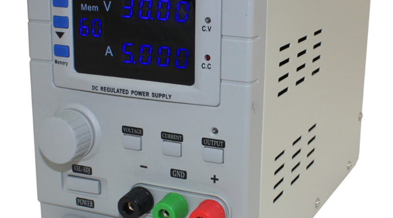
The first device I chose to integrate was the CSI305DB. I’ve had multiple people asking for the software to control the device, but as many of you may know, we only receive for redistribution the same material you receive in the unit, and therefore had nothing to give to any of these people. I considered, “How hard would it be to program some type of control software?” So, I gave it a go. I took the unit apart and starting looking up the datasheet for each IC from the USB port to the CPU. Unfortunately, that avenue didn’t give me anything. I then proceeded to start googling the unit to see if someone already reverse-engineered the protocol, or it was documented somewhere, but yet again I found nothing. I did however find one glimmer of hope. In a marketing video, I found someone using a program to control the unit with some software seemingly special built to the unit. I used our contact for the vendor, and they were kind enough to send me a download link to the software being used. It took some finagling to work, specifically, I had to run the program with the kernel emulation mode in Windows 10(my OS) for Windows XP, but it worked. However, this isn’t optimal and would be much better suited to having a straightforward program, possibly not even needing to be installed.
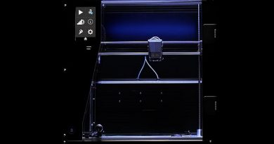
My first thought/action was to attach the process to windows debugger, but much to my chagrin the communication layer was several stack instructions in and would have taken forever to understand. Instead, then, I used my SDS1202X which has decode options prebuilt into the unit. However, there is a cheaper scope, the SDS1202X-E has those features. Using the scope, I probed the lines going directly to the CPU TX/RX lines during the startup sequence looking for the serial data. Turned out the lines were nominally high, and low was the data. I then played around with the baud rates until I thought it’s sending hex codes that at least seemed legitimate data packets. However, the problem still exists that the second line, which I had to figure out if it was TX or RX was still unrecognized data. So, I set the parity to even, and bingo decoding was finished. So, now I knew it was set at 9800 baud, with even parity. The next step was to decode the functions.
In this step, I used a program that virtualizes a COM port and displays the data being exchanged. Using the program isn’t completely necessary as you could continue to use the oscilloscope to capture the data, it would just take longer. Running the vendor program, I captured the data exchange selecting each one of the features in the program and documented the hex code being sent to the device. Once I sent all the commands, I analyzed the data, converted it to a c_string to see if there was a logical syntax, and sure enough, there was. The data was continuously being sent as ‘HPPSU0000H0000NY\n’. The first four zeros were the voltage in base 10 for the first two, and decimal for the last two. ie 10.2 volts => ‘1020’. The second set of four zeros was the amperage in base 10, and decimal for the last three. ie 1.234 amps => ‘1234’.
Now that I knew how it communicated, I used a program that allows me to open a com port and send commands in either a string or hex codes to emulate as though a program was sending the data. Sure enough, it worked. If I sent the code twice, the csi305db registered it was being controlled by a PC, and the values were set as I expected. However, the values would quickly return to normal after I stop sending the string. Therefore, only a program looping would truly be able to control the device effectively.
Time to write a Program…..read the second article about the software implementation, and the third article about SCPI and program control schemes.