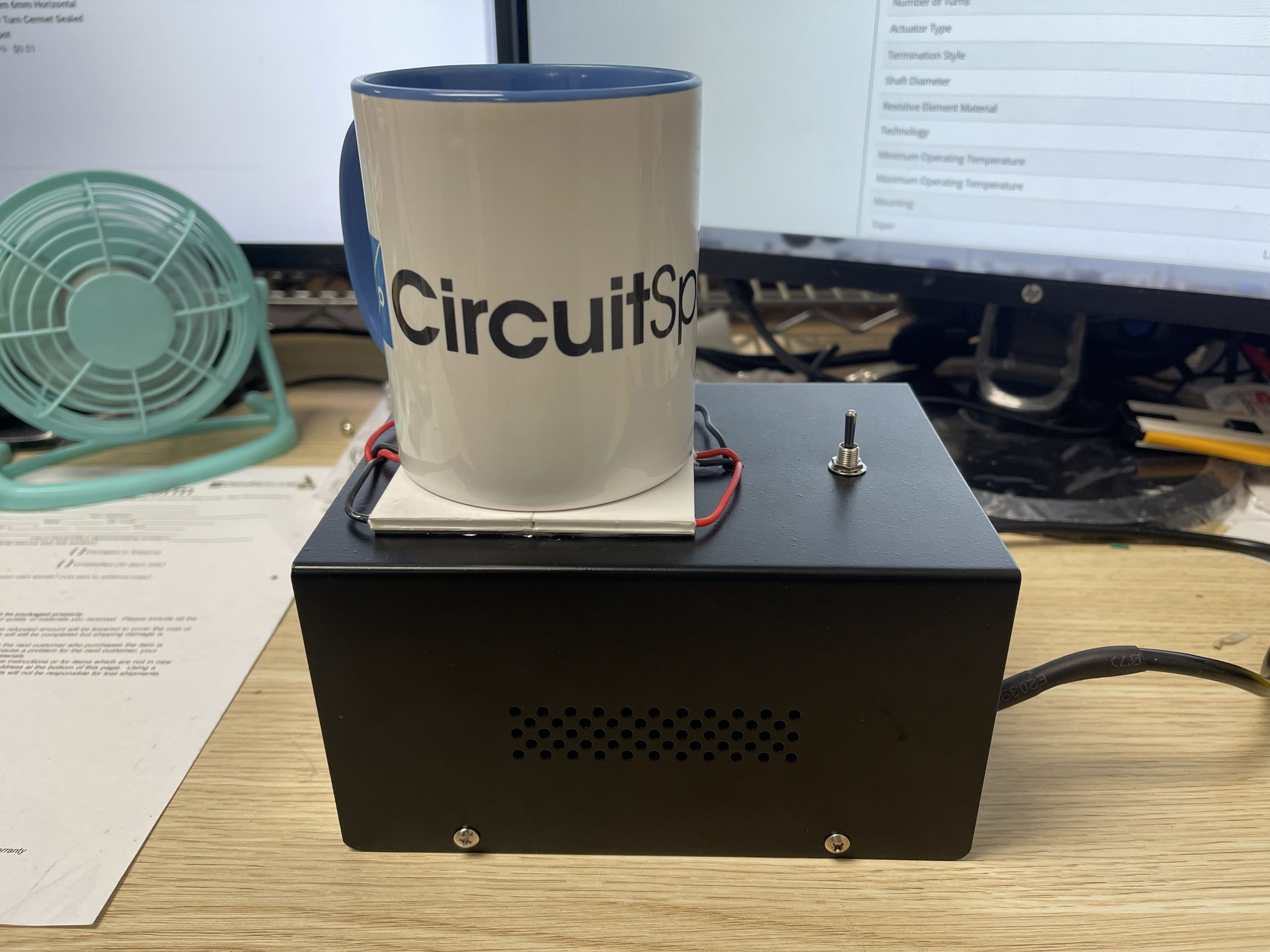
Thermoelectric Peltier Project: the Tabletop Heater-Cooler Device
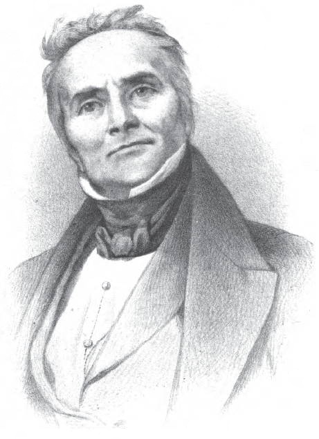
In this project we are going to build a Tabletop Heating-Cooling Device using Peltier’s thermoelectric principle. First, a brief history of peltier modules and the peltier effect…Jean Charles Athanase Peltier was 13 years old, and although he came from a poorly educated family in rural France, people began to notice he was gifted. It wasn’t until 1834, after a separate career dealing watches, that Peltier found that when he caused an electrical current to flow through a circuit made from two different conductors, a phenomenon happened. Depending on the direction of the current flow, one junction got hot and the other grew cold. This is now known as the Peltier effect.
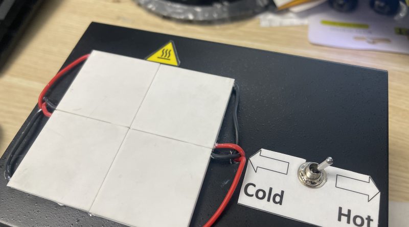
One of Circuit Specialists products includes peltier modules which take advantage of the peltier effect for real world applications. These modules can be used in devices where heating or cooling is desired. In our project we wanted to develop a simple application for the peltier modules that would also have some functionality. So we came up with the Thermoelectric Heating/Cooling plate project. We learned a lot during the project and we’ll share some of the lessons learned at the end.
Part list:
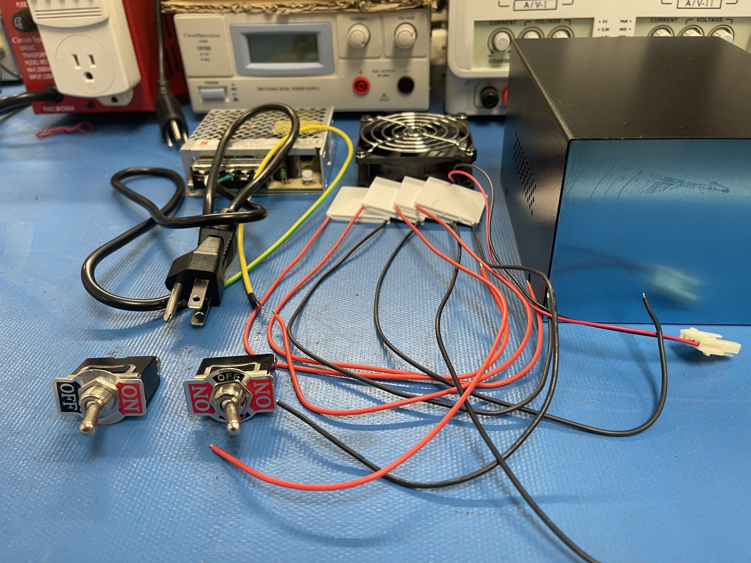
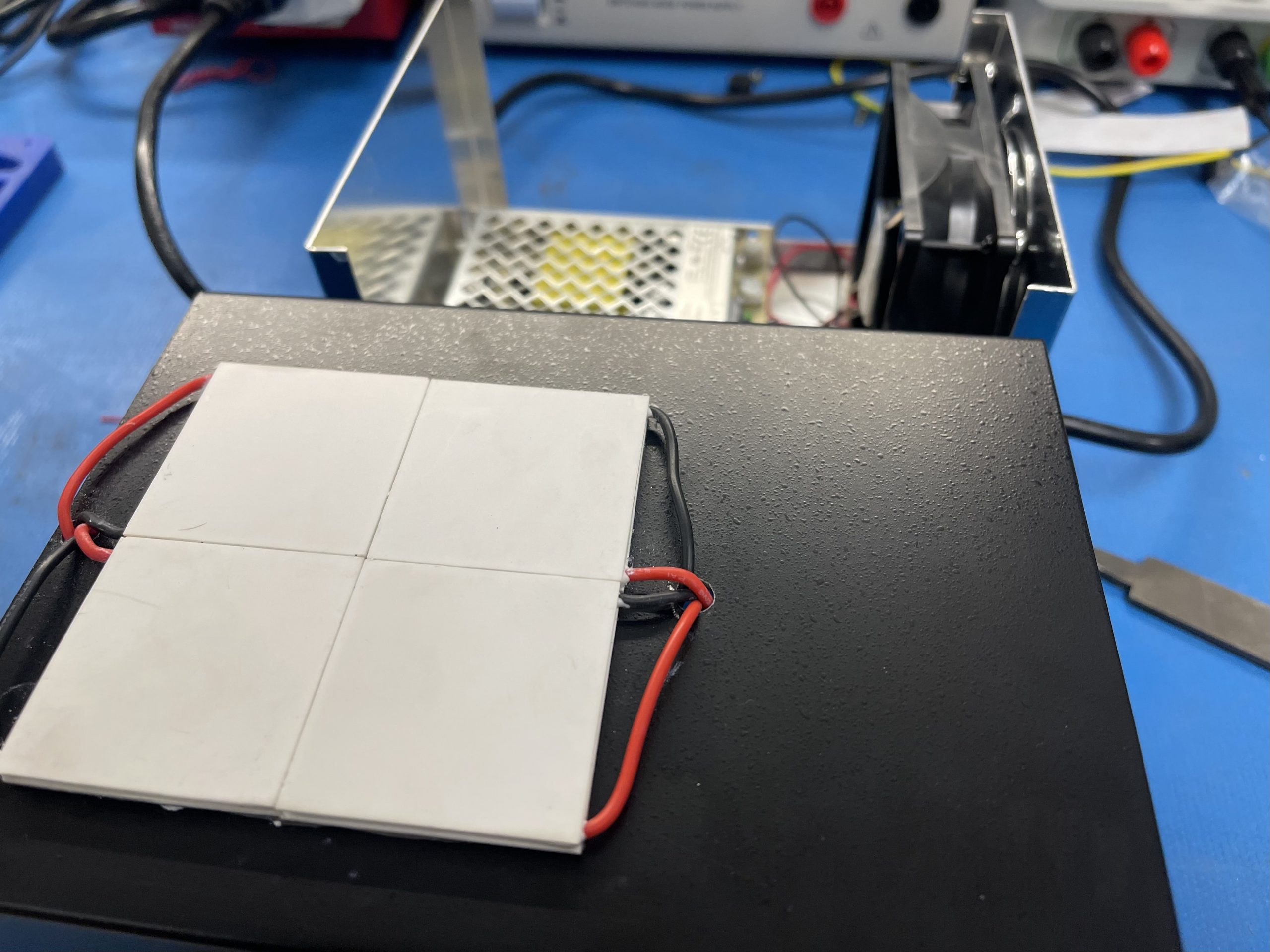
- Peltier thermoelectric modules. (we used 4 of these connected in series)
- Cooling fan.
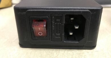
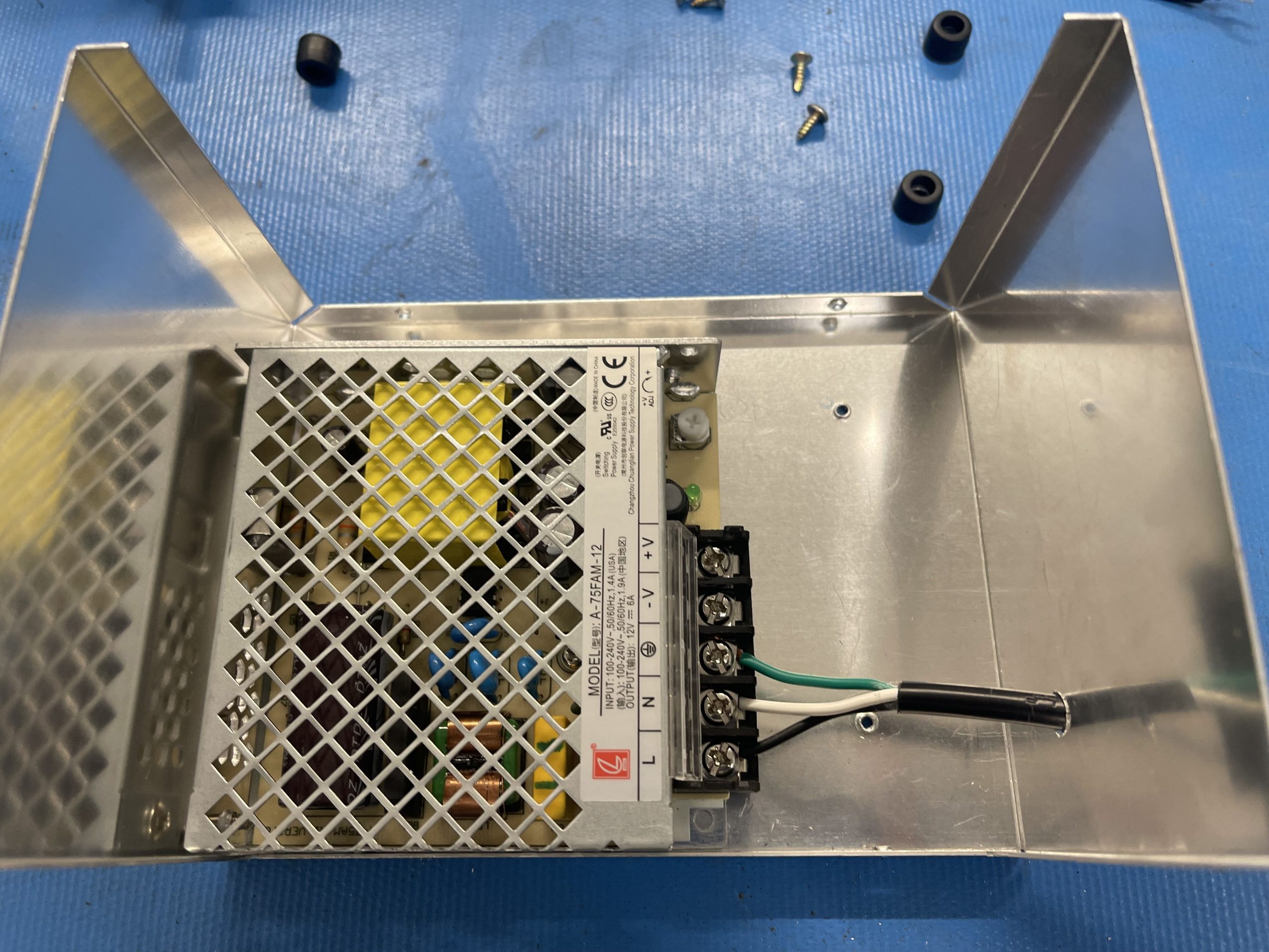
- AC-DC power Supply.
- Project box.
- Switch, double-pole double-throw (DPDT).
- Power cable.
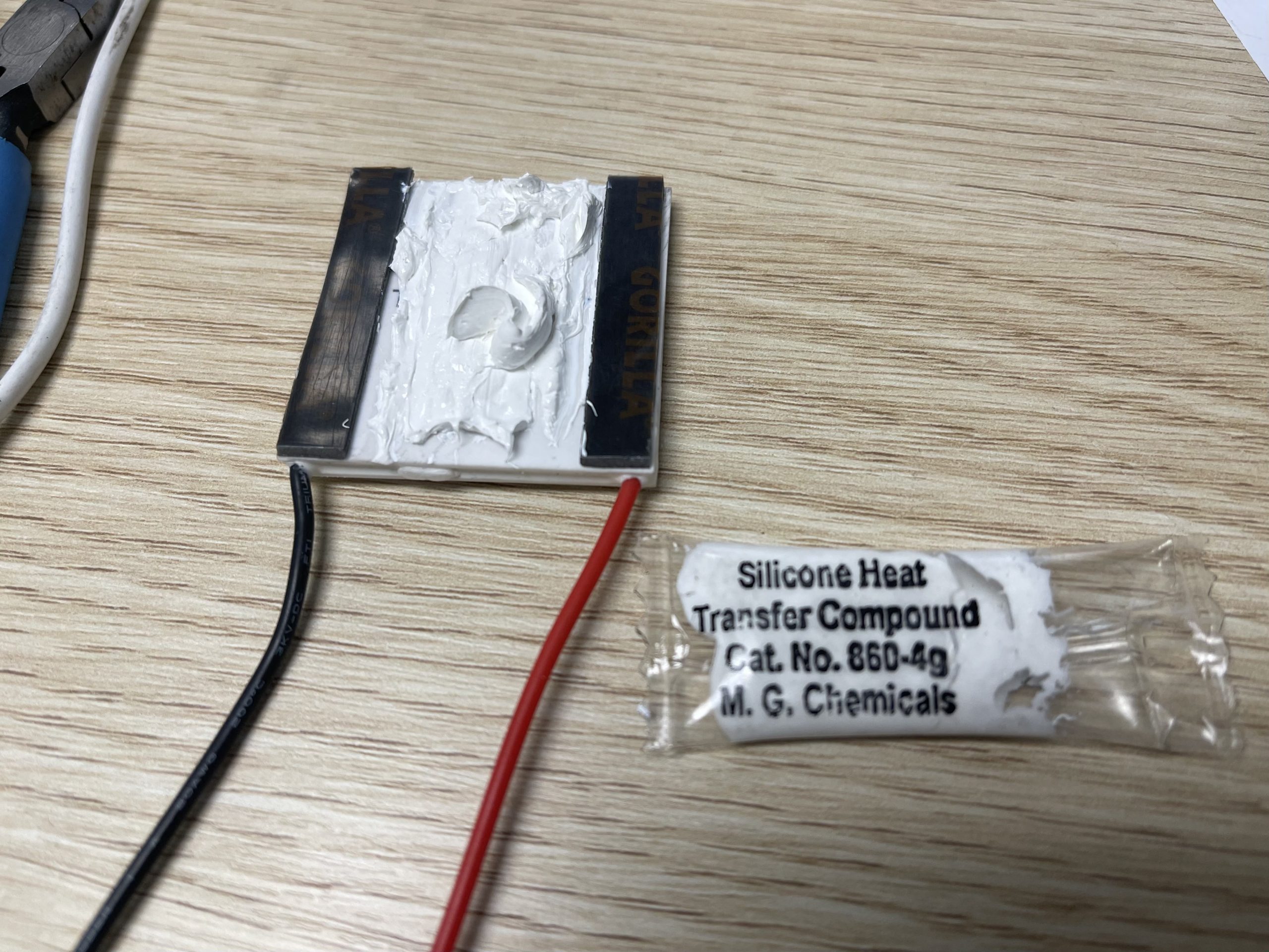
- Thermal adhesive a small tube.
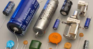
- 2200 uF capacitor
Build Instructions
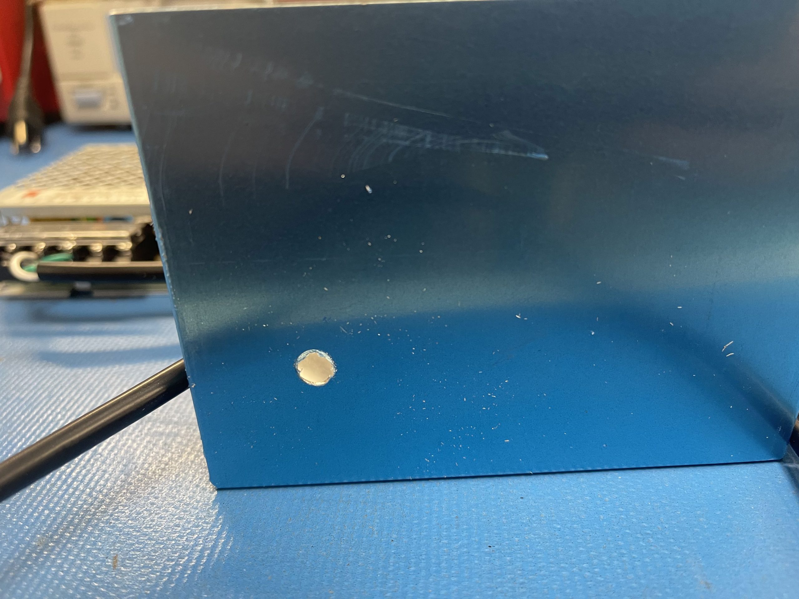
- Drill a hole to fit the stem of the DPDT switch in the center of your project box.
Run the power supply cable through the hole and wire accordingly.
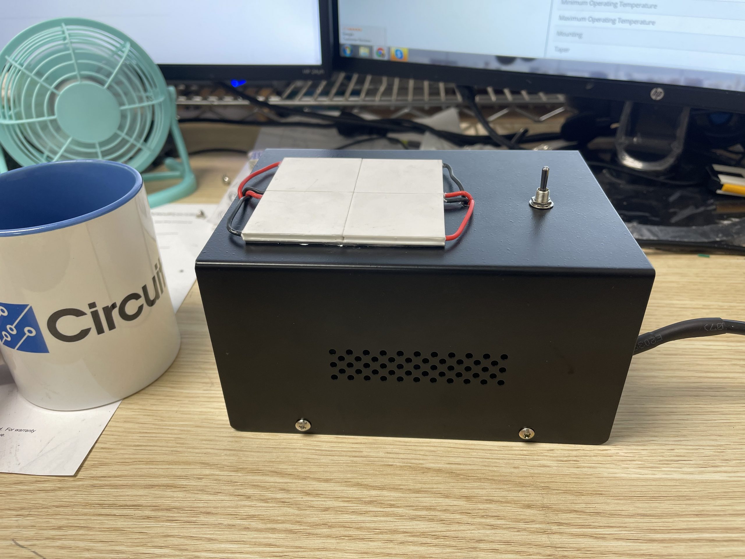
I use heavy-duty double side tape to glue the thermoelectric modules one atop the enclosure. Make sure to use some silicone heat transfer compound.
After gluing down the thermoelectric, drill 2 holes for the wires.
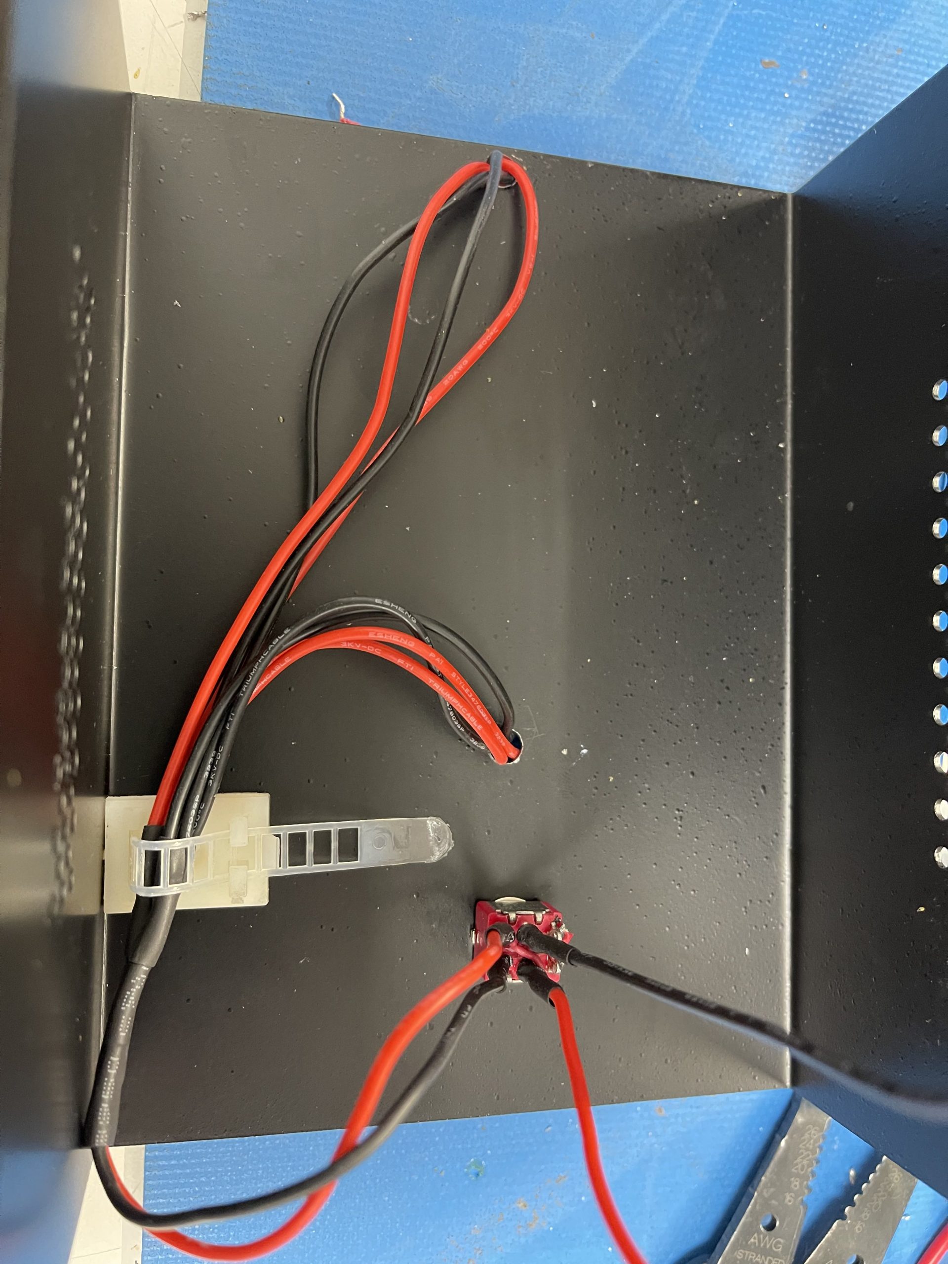
Wiring the switch according to the schematic below.
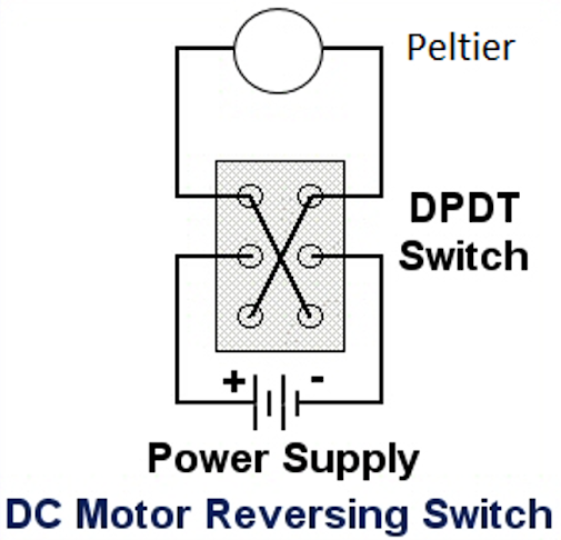
Drill a hole for the switch then solder the power and the thermoelectric module to the switch.
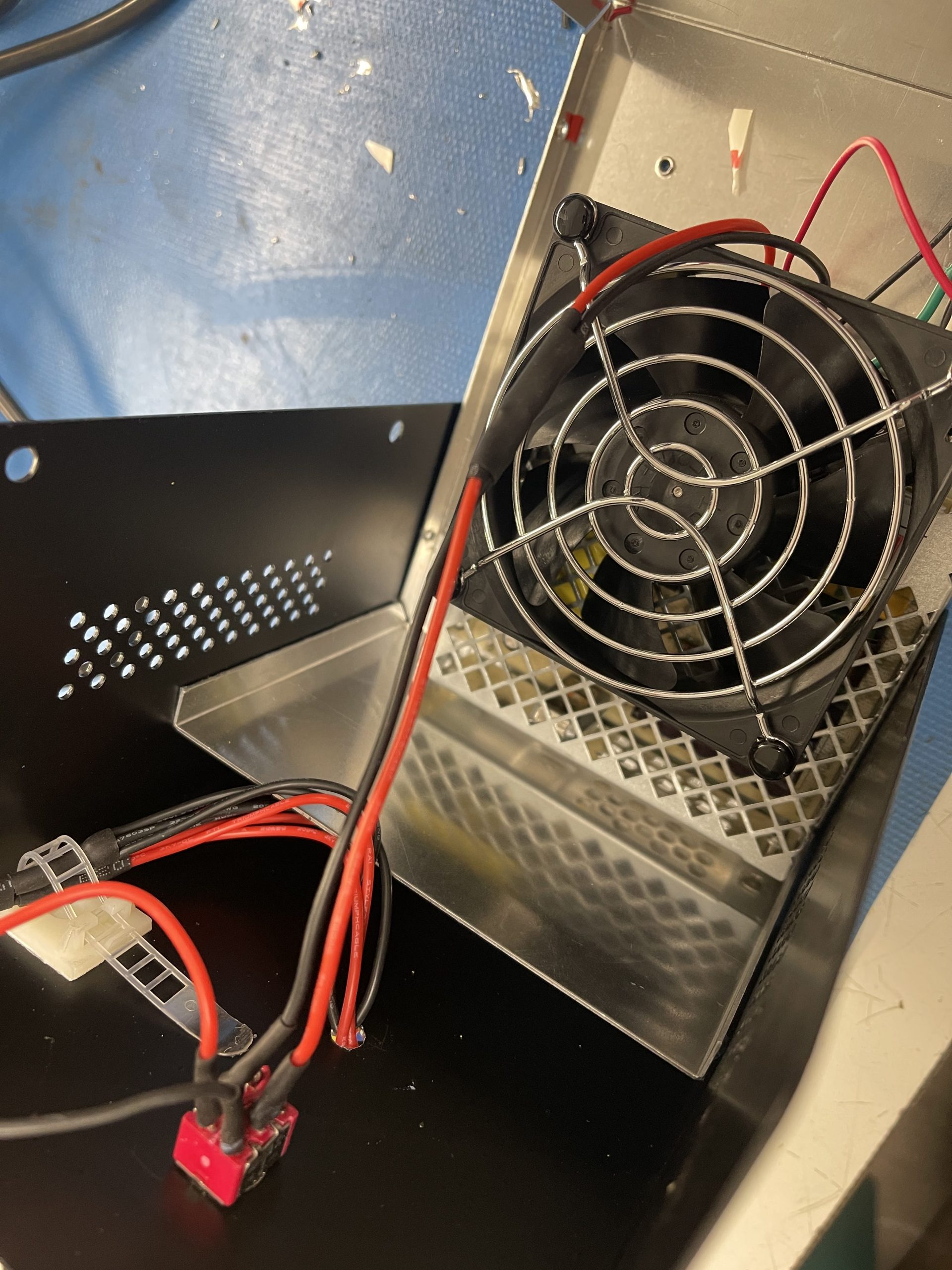
Install the fan on top of the power supply to make sure everything stays cool.
Reassemble the enclosure using the provided screws.
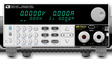
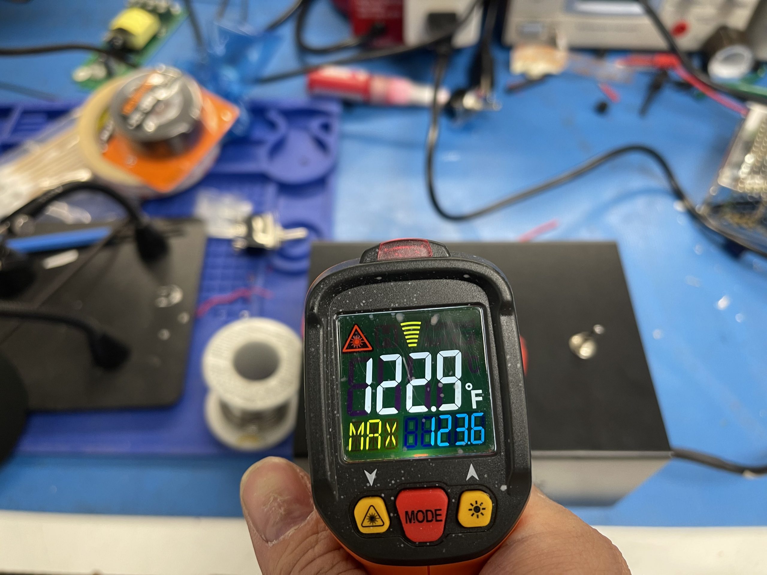
Finally, we can test for the max temperature that the device can produce.
Conclusion
The device can be improved in many places. For instance, a larger power supply can give a higher maximum temperature. Some heat sinks installed from the inside of the enclosure would also help increase the max temperature and lower the min temperature when cooling. Furthermore, a capacitor can really help with stabilizing the power. However, at Circuit Specialists, we want to make sure the project is safe for all ages so we keep the temperature around 130 degrees Fahrenheit.
Now you can sit back and enjoy your hot drink during the winter 😀
Get your very own Thermoelectric Heating/Cooling plate kit project here.