What is an Oscilloscope? Why is it important?
First, the short and sweet guide to an oscilloscope.
An oscilloscope is a device that allows you to see how voltage changes over time by displaying a waveform of electronic signals.
Why is that important?
Electronics such as lights, TVs, air-conditioning need electrical energy delivered by circuits.
A circuit is a path between two or more points which a current runs through.
Voltage is the electrical force that drives a current between two points.
Sometimes the voltage is not behaving correctly and you have to find out where in order to correct it.
Trying to find that problem without an oscilloscope is like driving a car with blindfolds on.
Now for the in-depth guide we will cover the following topics.
- What is an Oscilloscope?
- A Brief History of the Oscilloscope
- What is a Analog Oscilloscope?
- What is a Digital Oscilloscope?
- What Do the Systems On An Oscilloscope Do?
- Oscilloscope Terminology
So lets get started!
What is an Oscilloscope?
When you have circuits that have constant voltages a multimeter is a tool that can be used to measure a single number for the voltage. This becomes redundant when you start building more complex circuits. This is where an oscilloscope comes in handy.
An oscilloscope allows you to view how voltage changes over time. These voltages are called signals which are used to convey information such as an audio signal playing music on a loudspeaker.
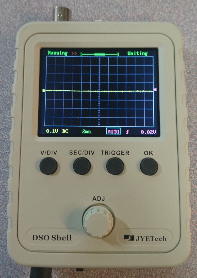
Some of the things that the display screen on an oscilloscope shows is the measured signal of the voltage using a graph. The voltage is represented on the vertical axis and time on the horizontal axis.
This display will allow you to determine if the behavior of your circuits is working correctly. It will also allow you to locate any problems within your circuit like unwanted signals called noise.
There are two types of oscilloscope; analog and digital. More on that later, because now we will cover a brief history of the oscilloscope.
A Brief History of the Oscilloscope
The oscilloscope was invented by a French physicist André Blondel in 1893. His device was able to register the values of electrical quantities such as alternative current intensity. An ink pendulum attached to a coil recorded the information on a moving paper tape. The first oscilloscopes had a very small bandwidth, between 10 and 19 kHz.
We will talk more about what bandwidth is later, but let’s wrap up our history lesson first.
Big developments came in 1897 when a German physicist Karl Ferdinand Braun invented a cathode ray tube (CRT). Oscilloscope development started to increase after WW2.
In 1946, two men by the name of Howard Vollum and Melvin Jack Murdock founded Tektronix, which today is one of the world’s leaders in producing oscilloscopes. In that same year, they invented their first oscilloscope, the model 511, with triggered sweep and 10 MHz bandwidth. Triggered sweep allowed stationary display of a repeating waveform.
Now let’s talk about the difference between an analog and digital oscilloscope.
What is an Analog Oscilloscope?
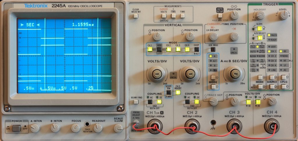
Analog oscilloscopes use high gain amplifiers to display the waveform on a green cathode ray tube (CRT) screen. Simply put, analog oscilloscopes are the older version of the oscilloscope that were first developed in the 1940s.
An analog oscilloscope comes equipped with one of several vertical channels, a horizontal channel, a trigger system, a time base, and a CRT module.
A vertical channel includes an attenuator, a preamplifier, an analog delay line and a vertical amplifier which amplifies a signal to the required level for the CRT model.
Horizontal channels come in two work modes, internal and external. Trigger systems have level adjustments that switch between increasing and decreasing levels.
What is a Digital Oscilloscope?
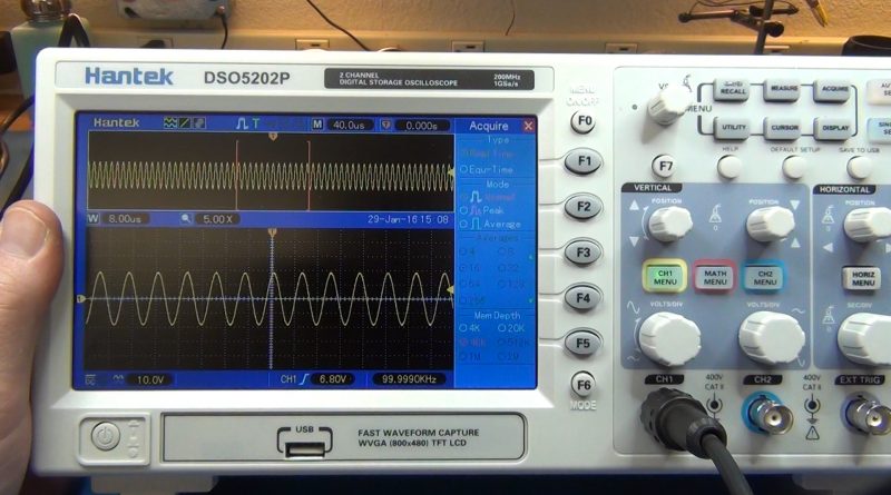
A digital oscilloscope uses a modern LCD screen. Almost all new oscilloscopes manufactured today are digital.
In a digital oscilloscope an extra step is used before the signal is displayed on the screen. The extra step converts the signal into a digital stream with an analog to digital converter, which removes the need for CRT type screens.
This reduces the complexity of the design and allows room for more features.
An example would be the addition of signal manipulation and complex mathematical operations that are now standard features for most digital oscilloscopes.
Now let’s talk about the systems on an oscilloscope.
What Do the Systems On An Oscilloscope Do?
A basic oscilloscope has four different systems, which are the vertical, horizontal, trigger and display system. Each of these systems allow you to measure specific things
The vertical system controls can be used to position and the scale the waveform vertically. It can also be used to set input coupling, bandwidth limit, and bandwidth enhancement.
The horizontal system can be used to find the sample rate and record length, along with positioning and scaling the waveform horizontally.
The trigger system allows you to stabilize repetitive waveforms and essentially snap a photo of the waveform. There are different types of trigger systems such as edge triggering, threshold triggering that respond to specific conditions in the incoming signal.
To collect the data that is read by the oscilloscope, you need a probe.
A probe has two main parts which are the ground clip and the probe tip. You would attach the ground clip to the ground reference for your circuit, then you would use the probe tip to poke around and measure voltages at various points throughout the circuit.
This is the basic overview of each system as there are many more things we could talk about, but this guide would be even longer if we did that!
We hope this guide to, ‘what is an oscilloscope?’ has been helpful thus far. Learning new things can be challenging but very rewarding as well!
While you have been reading this guide, you might have come across some vocabulary terms such as bandwidth and sample rate. What do those mean anyway?
Learning about a new thing requires learning new vocabulary, so below is a list of terms that will help, so follow along!
Oscilloscope Terminology
Bandwidth determines an oscilloscopes ability to measure a signal. As signal frequency rises, the oscilloscope’s ability to accurately display the signal, decreases. Without adequate bandwidth, all the other features on an oscilloscope mean nothing.
Rise time describes the frequency range of an oscilloscope. An oscilloscope with faster rise time will accurately capture details of fast transitions.
Sample rate is specified in samples per second or S/s and refers to how frequently an oscilloscope takes a snapshot of the signal. The higher the sample rate, the greater the detail of the displayed waveform.
Waveform capture rate is expressed as waveforms per second (wfms/s) which refers to how quickly an oscilloscope acquires waveforms.
Memory depth expressed as Mpts determines the amount of data that can be captured with each channel. The amount of samples an oscilloscope can store is limited therefore the waveform duration will be inversely proportional to the oscilloscope’s sample rate.
While there are a few more terms, these are the main ones that you should know about in regards to purchasing an oscilloscope. You can check out our guide for the best oscilloscopes for hobbyists for more information.
Conclusion
In summary the oscilloscope is a powerful tool that allows you to see how voltage changes over time by displaying a waveform of electronic signals.
We here at Circuit Specialists hope that this long (and short guide) has been helpful in answering your questions you had about oscilloscopes.
For more information about oscilloscopes and reviews check out the Circuit Specialist blog!
Questions? Comments? Please post below!