How to Build a Function Generator on the PBB-272C Powered Breadboard
Need to test circuitry but don’t have a waveform generator? A DIY signal generator that measures arbitrary waveforms is easy and affordable to make using the PBB-272C powered breadboard and a few other tools.
To create our analog function generator circuit, we will use a 555 timer to create a sine wave signal. Then we will validate our results using the Hantek 2D72 Handheld Oscilloscope.
But first, let’s review a few important terms (or you can jump straight to the tutorial!).
What is a Function Generator?
A function generator is a type of electronic test equipment that can generate different waveforms, including sine wave, square wave, or triangle waveform. Sine waves are waveforms that alternate in values during a cycle.
A function generator might also be called a waveform generator or signal generator, although signal generators refer to an entire group of test equipment that generates electrical signals. A signal generator that uses integrated circuits to generate waveforms may also be called a function generator ic.
What is a 555 Timer?
The 555 timer is an 8-pin chip. If you want to know all the pinouts of the 555 timers, see 555 Timer Pinout. The 555 timers can be obtained very cheaply from pretty much any electronic retailer.

What is a Sine Wave?
Sine waves are waveforms that alternate in values during a cycle. It has a peak value, which is the highest amplitude it attains, and a trough value, the lowest amplitude it obtains.

Sine waves are very common:
- Household electricity sockets come out of AC sine voltage signals.
- Function generators.
- Also used a lot in acoustics.
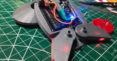
DIY Breadboard Function Generator in 5 Steps
Parts Needed
- 555 Timer Chip
- 2.2KΩ resistor
- 100nF ceramic capacitor
- 10nF ceramic capacitor
- 1μF ceramic capacitor
- 470μH inductor
- Power Breadboard 272C
In this circuit, we will connect the 555 timers to be in astable mode, which will produce square wave signals. Using an LC circuit, we will convert the square wave signal into a sine wave signal. The right values must be chosen for the LC resonant circuit, or else it will not work.
The sine wave generator circuit that we will build is shown below.

- Place the 555 timers in astable mode.
The astable mode can produce digital square waveforms that go back and forth between HIGH and LOW.
- Create an RC network circuit to place the 555 in astable mode.
Use the 2.2KΩ resistor and a 10nF capacitor to create an RC network circuit. Refer to the function generator schematic above for placement. This will help you filter and refine your signals.
- Connect to 4.5V power.
The power requirement of this circuit is 4.5V. This 4.5V goes to pin 8 and pin 4. Pin 1 is grounded.
- Calculate the RC network.
Use formula F= 1/2πRC.
For example, our test case formula looked like this: F= 1/2(3.14)(2.2KΩ)(10nF)= 7237Hz
Using this formula, we learned that the square wave signal has a frequency of approximately of 7.2KHz. However, we want this signal to turn into a sine wave.

- Create a resonant LC Circuit to produce a Sine Wave.
- The formula to calculate LC resonance is F = 1/2π√LC.
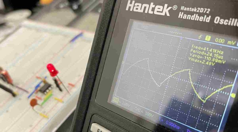
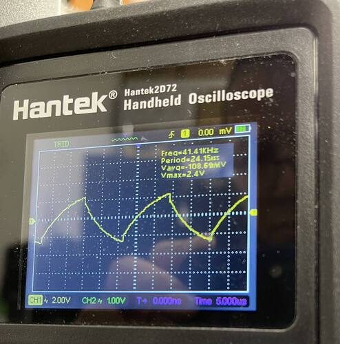
- The output square wave is approximately 41.4KHz.
- Calculate values for the LC network where the resonant frequency is just about 41.2KHz, with the values of 470μH for the inductor and 1μF for the capacitor.
By placing an LC resonant circuit at the output of the square wave, we can convert it into a sine wave.
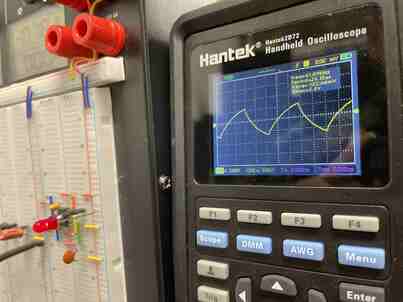
If you want to test your DIY function generator, you can use the Hantek 2D72 Handheld Oscilloscope to compare your results. The video below demonstrates how to hook up the oscilloscope.
Why it Works
In mathematics, a sine wave is the perfect model representation of resonance. When resonance is achieved through an LC circuit, the output signal will be a sine wave, because a sine wave represents resonance. Then the LC network resonates the square wave produced by the 555 timer chip into a sine wave.
.