How to Test and Calibrate Power Supply Voltage/Current Readings
Have you noticed that the readings on your power supply for voltage or current, don’t seem to match with your usage?
To test the power supply output voltage:
Grab your digital multimeter or whatever standard you can use to objectify your results, and check to see if intuition is indeed correct. Set your multimeter to VDC, and connect your probes to the supply in parallel.
To test your current reading:
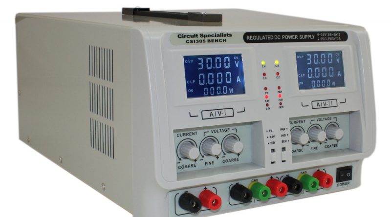
Set your digital multimeter to its amperage setting capable of tolerating >= 5 amps with your meter probes in series with the supply. To ensure you’re getting a valid reading, use an electronic load or resistor capable of dissipating the heat. Remember P=I^2*R. See the pictures below for an example of what the voltage test would look like.

If you find that your display doesn’t match what your meter reads, then the display does need to be calibrated. See below.
Caution: handle the unit with care after remove the enclosure as electrocution may be possible. We recommend this to be done by a train technician.

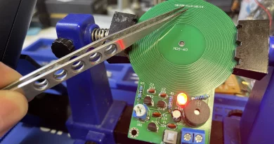
You’ll need to remove the back panel on whatever supply you have and locate the potentiometers on the back of the display, as seen below.

In this supply, the potentiometers are marked A for amperage, and U for voltage. Since we’re using the multimeter as the objective marker, that means the supply is too high, and needs to be adjusted to a lower value. Turn the knob until the values match, as seen below. This is of course assuming that your DMM is the device closest to the real value, something incredibly complicated to derive. Read more

If your voltage was out of spec, then repeat the same procedure, but adjusting the voltage pot instead. Once you’ve completed both, you’re done, and you can now trust your display readings again.
Article said, “If you find that your display doesn’t match what your meter reads, then the display does need to be calibrated.”
This can be very misleading. I have seen numerous examples of namebrand, high-cost supposedly quality DVMs that do NOT provide the degree of accuracy this article suggests to “calibrate” your PSU displays.
Don’t fall into the trap that just because a reading is digital and contains a lot of digits that the instrument is accurate to any great degree.
I’ve taken brand-new DVMs of the same model number, hooked them up in parallel and separately and measured various voltages and found consistently significant differences. Many of these meters are only accurate to 3 or 4 digits, AND then you add on a +/- 2% or 3% error range, AND then note that the last digit (often 3rd or 4th, even if the meter DISPLAYS 5 or 6 digits) can be +/- 1 digit. So a DVM may be off by 0.3 or 0.4 of a volt on the 20 volt scale.
The DVM itself may also be miscalibrated, have a low battery (e.g. a “9” volt battery at 8.9 volts)…WITHOUT showing “low batt” (which CAN still affect the displayed measurement value as much as several tenths of a volt).
I’ve seen DVMs where simply reversing the polarity resulted in a 0.3 VDC change in the absolute voltage…when it SHOULD show the same absolute value. For example, probes connected one way results in +12.1VDC display, and swap the polarity of the probe connections and it then reads -12.4VDC.
Then, if you change the voltage scale and repeat the tests, you may see entirely different values. Some DVM specs/manuals will show you that accuracy is dependent on the scale used.
In my opinion, one cannot ASSUME a typical consumer DVM is accurate to even 3 digits, and lab-grade DVM must be properly and timely certified/calibrated to even begin to assume it is showing a reasonably accurate value.
I should have also mentioned in my earlier comment, that some lab power supplies contain a non-DC component in their output. Digital PSUs in particular have been noted to have sometimes significant “noise” in their output…as much as 300 or 400mV at high-frequencies (e.g. 20kHz and up).
The problem is that DVMs can vary significantly in how they handle these non-DC components. It can depend whether the DVM uses any signal filtering (physical or software) in the DC scales, measures “true RMS” or not, and the correction algorithms they use can vary. In short, these non-DC components in the PSU output can add even more “error” to the “DC” voltage a particular DVM may be reporting. The result is that the “DC” component output in fact MAY be reported accurately by the PSU’s display, but the DVM may display a value that contains an slight offset that was created by including the non-DC component of the PSU’s output in its displayed value. This variation can be significant.
We appreciate your lengthy comment, however none of it applies here. To calibrate any device, you always use another higher accuracy/resolution device. If that device is out of calibration, then send it to a NIST lab and get the device calibrated, and they will perform the same procedure listed here, but with even better devices.