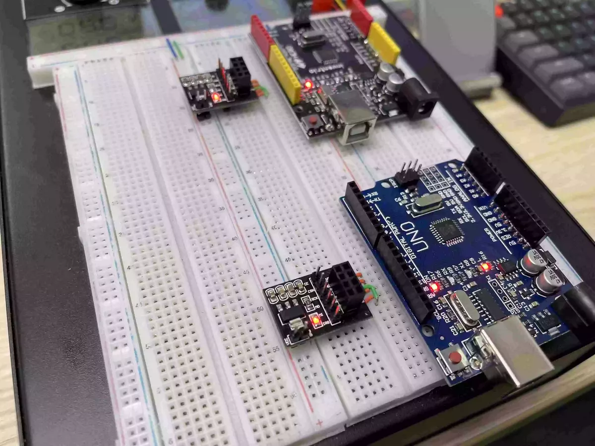
Wireless Communication On The Power Breadboard
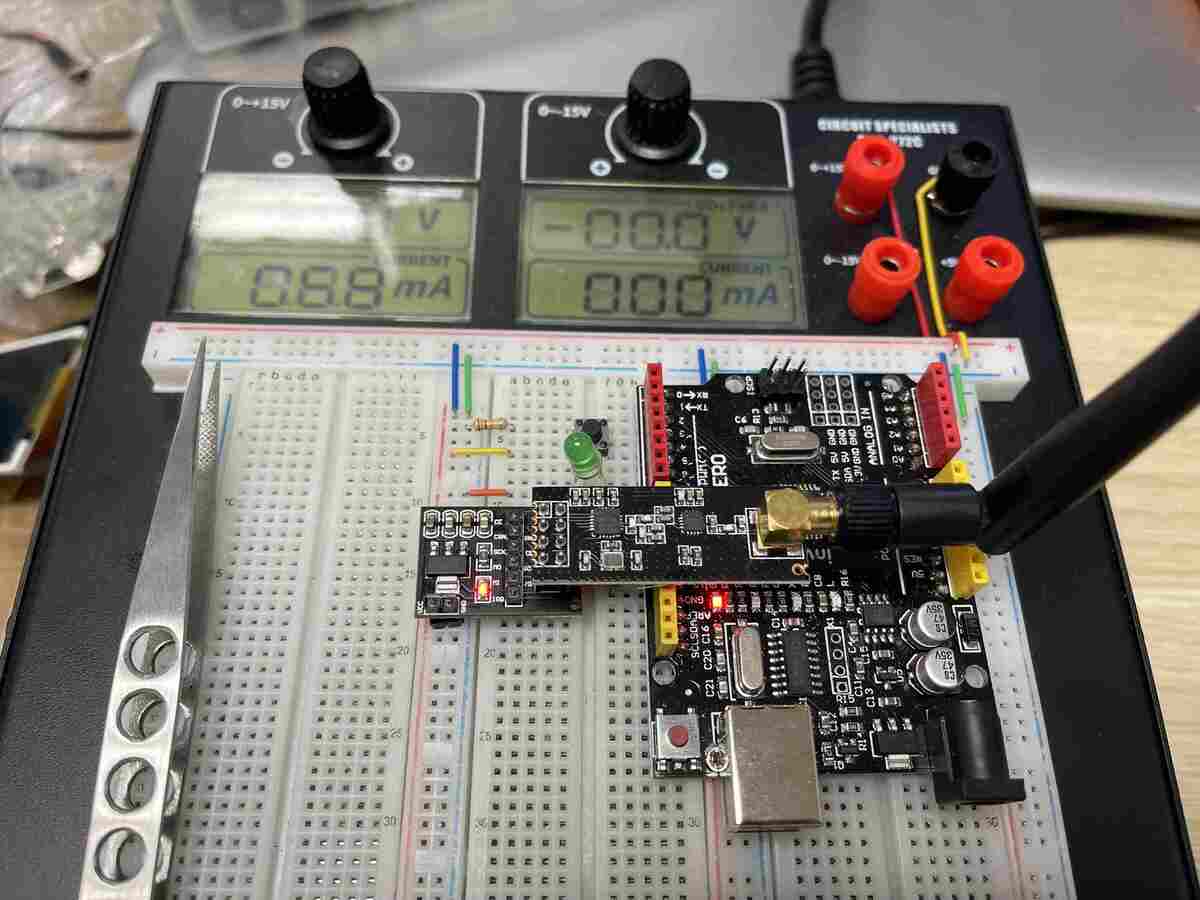
Building the Wireless Communication on the Power Breadboard provided many benefits. One of them is the ability to tap into a stable power source. We will also improve the original code by adding some cool features on the receiver end so wait for the surprise! Finally, we will use jumper wires to make all the connections to all the components together to archive a clean and neat finish.
Table of Content
- Part List
- What is the nRF24 communication module?
- How to Solder Header Pins?
- How to Solder Extention Pins to Header Pins?
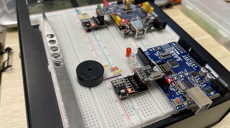
- Wiring: ( same for transmitter and receiver)
- The Bonus Code
- Conclusion.
Part List
- 2 Arduino
- 2 nRF24 Radio Modules
- 2 nRF 24 Breakout Boards
- Power Breadboard PBB-272 Series
- LEDs
- Jumper Wire
What is the nRF24 communication module?
One of the biggest benefits of the nRF24 is that the board can act as a dual-purpose device, where the nRF24 can turn an Arduino to be a transmitter and receiver. What this means is, that an Arduino can receive data and pass it on through a large network
This opens up the possibility of projects due to the flexibility of the board. Circuit Specialists want to change the norm of expensive communication hardware, that is what this project is all about, low cost and easy access.
How to Solder Header Pins?
There are a couple of tricks you can use to ensure a clean soldering job. The header pins will help connect the Arduino to the power breadboard so you want to make sure not to burn it and cause a loose connection.
How to Solder Extention Pins to Header Pins?
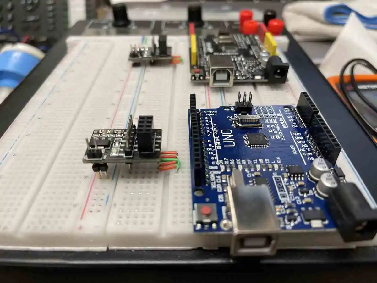
The nRF24 breakout board would need to add some extension pins so to the exiting harder pins because we want the board to be able to plug into the power beadboard PBB-272C.
Wiring: ( same for transmitter and receiver)
- VCC – 3.3V
- GND – GND
- CE – pin 9
- CSN – pin10
- SDK – pin 13
- MOSI – pin 11
- MISO – pin 12
The Code
The nRF24 breakout board is optional, it would keep the power to the nRF24 radio module constant and provide a better connection. If you decide to go with the nRF24 breakout board, the wiring will be the same however now you can supply it with 5V.
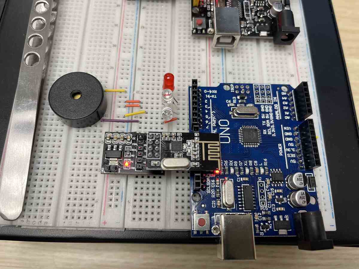
The code would be simple and straightforward when you press the switch button, the receiver reads the signal and turns on the LED.
The Transmitter code:
/*
  -----------------Note----------------------
  Date: 06-28-2022
  Project Name:
  Goal: Advance Radio_Module_Transmitter testing
  Author: Khang Nguyen
*/

#include <SPI.h>
#include <nRF24L01.h>
#include <RF24.h>

RF24 radio(9, 10); // CE, CSN

const byte address[6] = "00001";

const int T_Button = 2;
const int ledPin =  7;
int buttonState = 0;

struct Data_Package
{
  byte L_Switch;
  byte R_Switch;
  byte Knob_Value;
};

Data_Package data;

void setup()
{
  pinMode(ledPin, OUTPUT);

  Tranmitter_Setup();

}
void loop()
{
  delay(5);
  radio.stopListening();
 /*
    int angleValue = 232;
    radio.write(&angleValue, sizeof(angleValue));
*/

   buttonState = digitalRead(T_Button);
   radio.write(&buttonState, sizeof(buttonState));

   if (buttonState == HIGH) {
    // turn LED on:
    digitalWrite(ledPin, HIGH);
  } else {
    // turn LED off:
    digitalWrite(ledPin, LOW);
  }
   delay(5);

}

void Tranmitter_Setup()
{
  radio.begin();
  radio.openWritingPipe(address);
  radio.setAutoAck(false);
  radio.setDataRate(RF24_250KBPS);
}
The receiver code:
/*
  -----------------Note----------------------
  Date: 06-28-2022
  Project Name:
  Goal: Advance Radio_Module_Reciver testing
  Author: Khang Nguyen
*/

#include <SPI.h>
#include <nRF24L01.h>
#include <RF24.h>

RF24 radio(9, 10); // CE, CSN

const byte address[6] = "00001";

boolean buttonState = 0;

int data_T;
//int LED = 2;

  const int RedLED=2; //(Nano D6) uno pin 6
  const int WhiteLED=3; //(Nano D7) uno pin 7
  const int BlueLED=4;

const int BuzzerPin=5;


unsigned long lastReceiveTime = 0;
unsigned long currentTime = 0;

unsigned long previousMillis = 0;
const long interval = 100;

void setup()
{
  Reciever_Setup();
  Serial.begin(9600);

  pinMode(RedLED, OUTPUT); //LED configured as output
  pinMode(WhiteLED, OUTPUT); //LED configured as output
  pinMode(BlueLED, OUTPUT); //LED configured as output

  pinMode(BuzzerPin, OUTPUT); //Buzzer configured as output
}

void loop()
{
 delay(5);
  radio.startListening();
  if ( radio.available())
  {
    while (radio.available())
    {
    /*   int angleV = 0;
      radio.read(&angleV, sizeof(angleV));
      Serial.print("angleV");Serial.println(angleV);*/

       radio.read(&buttonState, sizeof(buttonState));
        if (buttonState == HIGH) {
         Serial.println("Button Press!");
         USNationalAnthem();
        //digitalWrite(LED, HIGH);
        }
  else
        {
        //digitalWrite(LED, LOW);
        }
    }
    delay(5);
  }
}
The Bonus Code
This part of the code would make the buzzer play the National Anthem
void Reciever_Setup()
{
  radio.begin();
  radio.openReadingPipe(0, address);
  radio.setAutoAck(false);
  radio.setDataRate(RF24_250KBPS);
  radio.setPALevel(RF24_PA_LOW);
  radio.startListening(); //  Set the module as receiver
}


  int n=1000; //declaring the integer this value will change with each song
  int DurationOn=n; //declaing integer for later on will be used in stacatto calculations
  int DurationRest=n; //declaing integer for later on will be used in stacatto calculations

  //sum of x & y should be 1 I have more notes on this later on
  float x=.66; //declaring float for time on
  float y=.34; //declaring float for time off

  //rate at which lights randomly flash while waiting button input
  int Twinkle_Rate=250; //note that if increased drastically buttons may not respond 100% of the time
  //lower twinkle rate improves button press response

    int Note1=233; //3Bb   233Hz
  int Note2=294; //4D    294Hz
  int Note3=330; //4E    330Hz
  int Note4=349; //4F    349Hz
  int Note5=392; //4G    392Hz
  int Note6=440; //4A    440Hz
  int Note7=466; //4Bb   466Hz
  int Note8=523; //5C    523Hz
  int Note9=587; //5D    587Hz
  int Note10=622; //5Eb  622Hz
  int Note11=698; //5F   698Hz

 //**************************************************************SingleDW function
void SingleDWwithNote(int HZ, int TurnOn, int Duration, int Staccato){
  //Hertz at which note is (references Note#)
  //turn on= pin (red/white/blue LED) that will be tuned on
  //duration is for how long
  //Staccato 1=yes, 0=no results in slightly shortened note, or a high int x value as just a brief pause


  if (Staccato==1){DurationOn=Duration*x;} //how long tone & lights are on is DurationShort
  else if (Staccato==0){DurationOn=Duration;}

    digitalWrite(TurnOn, HIGH);

    tone(BuzzerPin, HZ, DurationOn);
    delay(DurationOn);

    digitalWrite(TurnOn, LOW);

  if (Staccato==1) {
    DurationRest=Duration*y;
    delay(DurationRest);
    }
}


  void USNationalAnthem(){
  n=577; //rate at which sound plays calulated from: 60,000 (ms/BPM factor) / 104 BPM = 577 ms
  /*
    quarter note value is n
    half note value in n*2
    eighth notes it n/2
    dotted eights note is n*3/4
  */

  //x & y integers are for staccato/adding rest after a note
  //note that x+y must =1 or the int. n rate will be thrown off
  //decrease x and increase y though to make the notes more pronouced and jumpy/upbeat
  x=.92; //true stacatio is about 1/2 or 2/3 value so x value around .5 to .7 for a true staccato
  y=.08; //1.00-.92(x value) =.08

  //bars 1-5, lines 1
  SingleDWwithNote(Note4, RedLED, n*3/4, 1);
  SingleDWwithNote(Note2, WhiteLED, n/4, 1);
  SingleDWwithNote(Note1, RedLED, n, 1);
  SingleDWwithNote(Note2, WhiteLED, n, 1);
  SingleDWwithNote(Note4, RedLED, n, 1);
  SingleDWwithNote(Note7, WhiteLED, n*2, 1);
  SingleDWwithNote(Note9, BlueLED, n*3/4, 1);
  SingleDWwithNote(Note8, WhiteLED, n/4, 1);
  SingleDWwithNote(Note7, RedLED, n, 1);
  SingleDWwithNote(Note2, WhiteLED, n, 1);
  SingleDWwithNote(Note3, BlueLED, n, 1);
  SingleDWwithNote(Note4, RedLED, n*2, 1);
  SingleDWwithNote(Note4, RedLED, n/2, 1);
  SingleDWwithNote(Note4, RedLED, n/2, 1);

  //bar6-9 line 2
  SingleDWwithNote(Note9, BlueLED, n*3/2, 1);
  SingleDWwithNote(Note8, WhiteLED, n/2, 1);
  SingleDWwithNote(Note7, RedLED, n, 1);
  SingleDWwithNote(Note6, BlueLED, n*2, 1);
  SingleDWwithNote(Note5, WhiteLED, n/2, 1);
  SingleDWwithNote(Note6, BlueLED, n/2, 1);
  SingleDWwithNote(Note7, RedLED, n, 1);
  SingleDWwithNote(Note7, RedLED, n, 1);
  SingleDWwithNote(Note4, BlueLED, n, 1);
  SingleDWwithNote(Note2, WhiteLED, n, 1);
  SingleDWwithNote(Note1, BlueLED, n, 1);
  SingleDWwithNote(Note4, RedLED, n*3/4, 1);
  SingleDWwithNote(Note2, WhiteLED, n/4, 1);

  //bars 10-13 line 3
  SingleDWwithNote(Note1, RedLED, n, 1);
  SingleDWwithNote(Note2, WhiteLED, n, 1);
  SingleDWwithNote(Note4, RedLED, n, 1);
  SingleDWwithNote(Note7, WhiteLED, n*2, 1);
  SingleDWwithNote(Note9, BlueLED, n*3/4, 1);
  SingleDWwithNote(Note8, WhiteLED, n/4, 1);
  SingleDWwithNote(Note7, RedLED, n, 1);
  SingleDWwithNote(Note2, WhiteLED, n, 1);
  SingleDWwithNote(Note3, BlueLED, n, 1);
  SingleDWwithNote(Note4, RedLED, n*2, 1);
  SingleDWwithNote(Note4, RedLED, n/2, 1);
  SingleDWwithNote(Note4, RedLED, n/2, 1);

  //bar 14-17, line 4, end of page 1
  SingleDWwithNote(Note9, BlueLED, n*3/2, 1);
  SingleDWwithNote(Note8, WhiteLED, n/2, 1);
  SingleDWwithNote(Note7, RedLED, n, 1);
  SingleDWwithNote(Note6, BlueLED, n*2, 1);
  SingleDWwithNote(Note5, WhiteLED, n/2, 1);
  SingleDWwithNote(Note6, BlueLED, n/2, 1);
  SingleDWwithNote(Note7, RedLED, n, 1);
  SingleDWwithNote(Note7, RedLED, n, 1);
  SingleDWwithNote(Note4, BlueLED, n, 1);
  SingleDWwithNote(Note2, WhiteLED, n, 1);
  SingleDWwithNote(Note1, RedLED, n, 1);
  SingleDWwithNote(Note9, BlueLED, n/2, 1);
  SingleDWwithNote(Note9, BlueLED, n/2, 1);

  //bars 18-21, line 5, start of page 2
  SingleDWwithNote(Note9, BlueLED, n, 1);
  SingleDWwithNote(Note10, RedLED, n, 1);
  SingleDWwithNote(Note11, WhiteLED, n, 1);
  SingleDWwithNote(Note11, WhiteLED, n*2, 1);
  SingleDWwithNote(Note10, RedLED, n/2, 1);
  SingleDWwithNote(Note9, BlueLED, n/2, 1);
  SingleDWwithNote(Note8, WhiteLED, n, 1);
  SingleDWwithNote(Note9, BlueLED, n, 1);
  SingleDWwithNote(Note10, RedLED, n, 1);
  SingleDWwithNote(Note10, RedLED, n*2, 1);
  SingleDWwithNote(Note10, RedLED, n, 1);

  //bars 22-25, line 6
  SingleDWwithNote(Note9, WhiteLED, n*3/2, 1);
  SingleDWwithNote(Note8, BlueLED, n/2, 1);
  SingleDWwithNote(Note7, WhiteLED, n, 1);
  SingleDWwithNote(Note6, RedLED, n*2, 1);
  SingleDWwithNote(Note5, BlueLED, n/2, 1);
  SingleDWwithNote(Note6, RedLED, n/2, 1);
  SingleDWwithNote(Note7, WhiteLED, n, 1);
  SingleDWwithNote(Note2, BlueLED, n, 1);
  SingleDWwithNote(Note3, RedLED, n, 1);
  SingleDWwithNote(Note4, WhiteLED, n*2, 1);
  SingleDWwithNote(Note4, RedLED, n, 1);

  n=n*1.08; //60,000 / 96 bpm= 625 ms; just a slight retard

  //bars 26-28, line 7

  SingleDWwithNote(Note7, WhiteLED, n, 1);
  SingleDWwithNote(Note7, WhiteLED, n, 1);
  SingleDWwithNote(Note7, WhiteLED, n/2, 1);
  SingleDWwithNote(Note6, BlueLED, n/2, 1);
  SingleDWwithNote(Note5, RedLED, n, 1);
  SingleDWwithNote(Note5, RedLED, n, 1);
  SingleDWwithNote(Note5, RedLED, n, 1);
  SingleDWwithNote(Note8, WhiteLED, n, 1);
  SingleDWwithNote(Note10, RedLED, n/2, 1);
  SingleDWwithNote(Note9, BlueLED, n/2, 1);
  SingleDWwithNote(Note8, WhiteLED, n/2, 1);
  SingleDWwithNote(Note7, RedLED, n/2, 1);

  //bars 29-30
  SingleDWwithNote(Note7, RedLED, n, 1);
  SingleDWwithNote(Note6, BlueLED, n*2, 1); //2x for holding
  SingleDWwithNote(Note4, RedLED, n/2, 1);
  SingleDWwithNote(Note4, RedLED, n/2, 1);
  SingleDWwithNote(Note7, BlueLED, n*3/2, 1);
  SingleDWwithNote(Note8, WhiteLED, n/2, 1);
  SingleDWwithNote(Note9, BlueLED, n/2, 1);
  SingleDWwithNote(Note10, RedLED, n/2, 1);

  n=n*1.2; //large retard

  //bars 31-34 end of song
  SingleDWwithNote(Note11, WhiteLED, n*2, 1); //extra hold on free
  SingleDWwithNote(Note7, RedLED, n/2, 1);
  SingleDWwithNote(Note8, WhiteLED, n/2, 1);
  SingleDWwithNote(Note9, BlueLED, n*3/2, 1);
  SingleDWwithNote(Note10, RedLED, n/2, 1);
  SingleDWwithNote(Note8, WhiteLED, n, 1);
  SingleDWwithNote(Note7, RedLED, n*3, 1); //only holding for 3 values

  //rasie all notes by 3 steps
  //1.06 derived from music theory. Take a note in hertz and then divide by the
  //note below it (sharps and flats count as a note) all round to 1.06
  //You can delete this next paragraph to avoid frequency changes or change it up if you want
  Note1=Note1*1.06*1.06*1.06;
  Note2=Note2*1.06*1.06*1.06;
  Note3=Note3*1.06*1.06*1.06;
  Note4=Note4*1.06*1.06*1.06;
  Note5=Note5*1.06*1.06*1.06;
  Note6=Note6*1.06*1.06*1.06;
  Note7=Note7*1.06*1.06*1.06;
  Note8=Note8*1.06*1.06*1.06;
  Note9=Note9*1.06*1.06*1.06;
  Note10=Note10*1.06*1.06*1.06;
  Note11=Note11*1.06*1.06*1.06;

  buttonState == LOW;
}
Check out the video from the link for audio: https://youtube.com/shorts/RZmgAKUz0MU
Conclusion
The Wireless Communication Network Developer (WCND) kit has been covered before here in our Maker Pit. However, building Wireless Communication on the Power Breadboard provided many benefits. Firstly, use the Power Breadboard PBB-272C to make the archive a clean look upon finish. Secondly, the ability to tap into the power source anywhere on the boards. Moreover, we also want to celebrate the Fourth of July by programming the National Anthem when the button is triggered.