
Click to expand
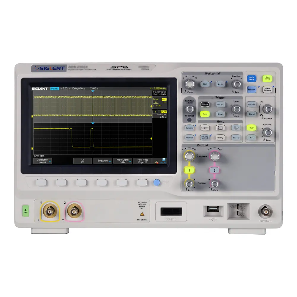
Siglent SDS2202X 200MHz 2 Ch Super Phosphor Oscilloscope
by SIGLENT
SKU: SDS2202X
$1,116.50
Availability: Out Of Stock
We're sorry, this item is discontinued.
For help finding an alternative product, please call 1-800-528-1417 or email sales@circuitspecialists.com and we'll be happy to assist.
Reviews