Testing a Breadboard for Continuity & Isolation
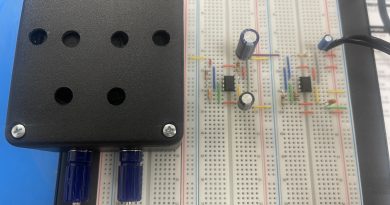
Consisting of multiple columns and rows connected beneath by metal strips, a breadboard is a plastic grid used for creating and testing electronic circuits designed for use with through-hole components that have connection legs or pins you can insert into the holes of the breadboard. Because all the holes are connected, the individual columns and rows on the breadboard have continuity and are isolated from the other columns and rows. You can check both continuity and isolation using a digital multimeter.
You will need two jumper wires, which may have been included with your breadboard. Only use jumpers that fit the breadboard. Connect a jumper wire to both multimeter probes. If your multimeter has straight pin-type probes, use alligator clips to connect the jumper wires to the probes. Set the multimeter to test resistance, typically listed as ohms.
A bus consists of two columns labelled “+” and “-” that are generally used for ground and power connections. Locate one on the breadboard. If you have a large breadboard, there may be several buses from which to choose. Next you will locate a row consisting of a group of five holes labelled “A” to “E” or “F” to “J”. Find the row number listed on the left side of the breadboard.
You test the continuity of the “+” column for a given bus by touching one of the multimeter probes to the top hole and touching the other probe to the bottom hole in the same column. The multimeter will read around zero if the device under test has continuity. You test the continuity of the “-” column for that bus the same way: touch one multimeter probe to the top hole and other probe to the bottom hole of the same column.
If want to check that the “+” column is isolated from the “-” column touch one probe to any hole in the “+” column and the other probe to any hole in the “-” column. The multimeter should display infinite resistance, typically represented by the number one followed by a series of dashes, meaning the two bus columns are not electrically connected (i.e. isolated).
You test a row’s continuity by touching one probe to hole labelled “A” and the other to “E”. If the multimeter reads nearly zero the row has continuity. Touch one probe to the “A” and the other probe to “J” in the same row to ensure the row is isolated from adjacent rows. You test the isolation of one row from another by touching one probe to “A” and the other probe to the “A” hole in the row below. The row is isolated from the one below it if the multimeter reads infinite.
If you question the functionality of other sections of the breadboard, repeat these tests in those places.