Smart House Project Series – Part 1
A Smart House will be the next smartphone. The technology that encompasses a smart house will become the new normal for modern-day homeowners. Smart houses range from basic to advanced depending on the sensors that are installed in the house and the operating system. The ARD-02, 201 Arduino Basics Starter Kit, comes with everything to build a Smart House Model. The kit comes equipped with a temperature sensor for temperature control, LED lights for the house lighting system, sound for the security system, servo motors, and stepper motors for a wide range of motion control.
We want to take advantage of the lessons that come with the ARD-02 Kit, we will use their provided code and do a little modification to work with the smart house project, I will attach the link for the ARD-02 example code below for reference.
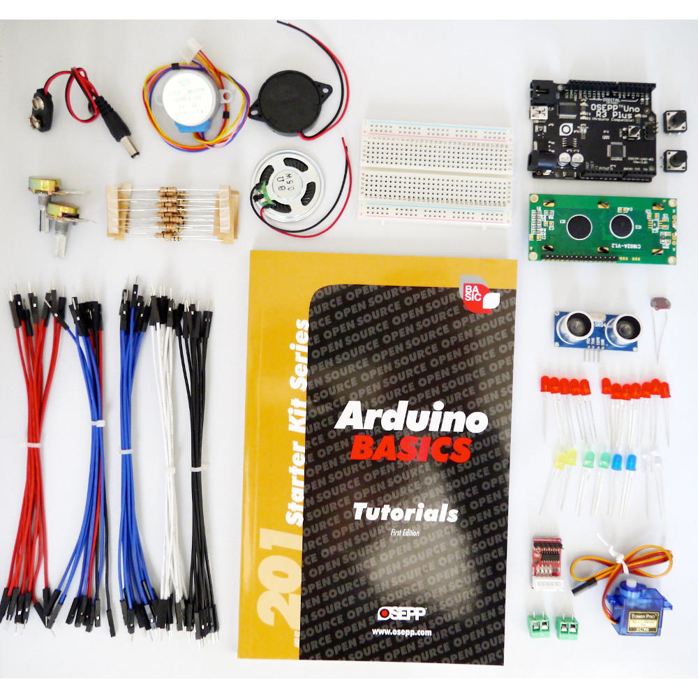
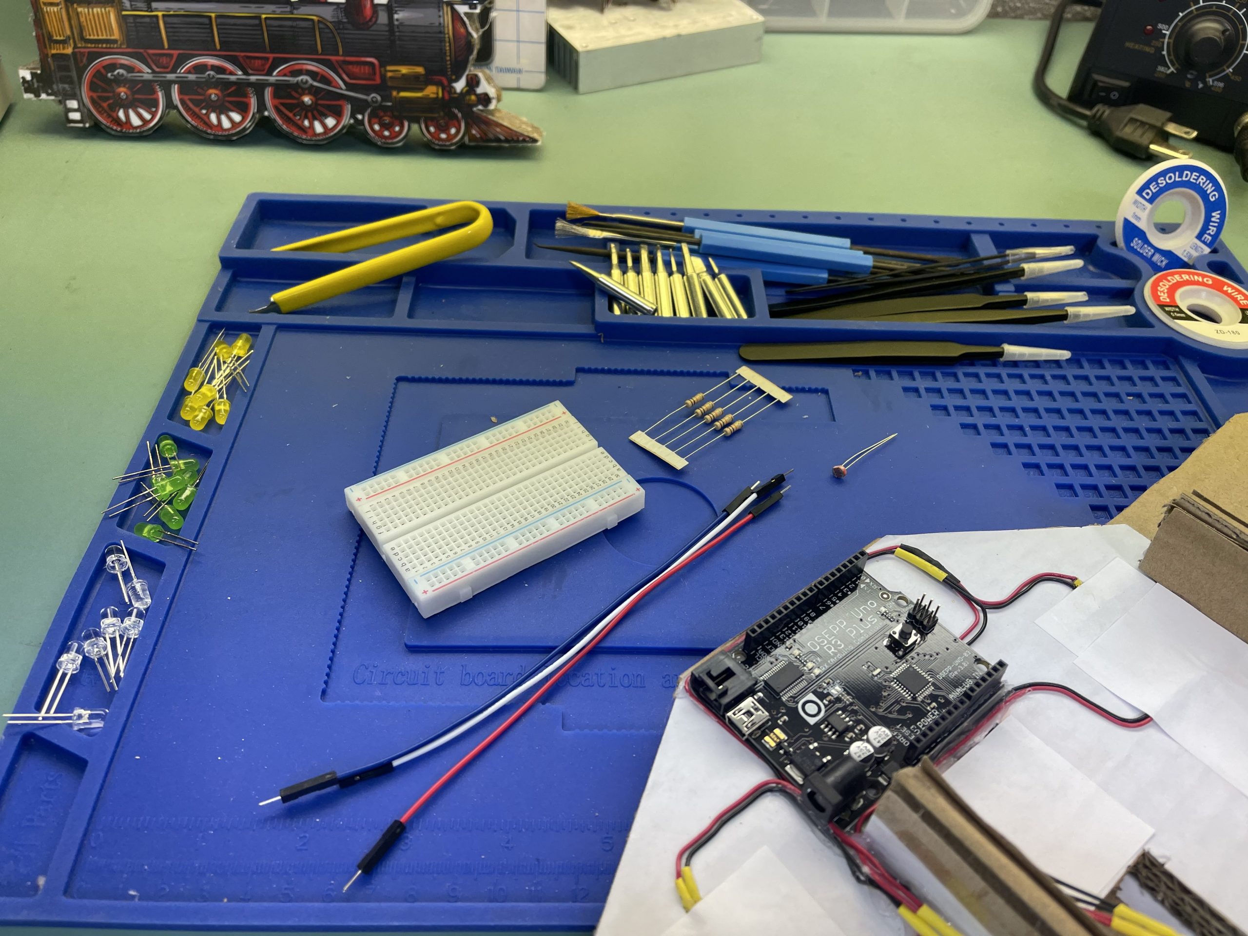
Part list:
ARD-02 Arduino Basic Kit
LEDs
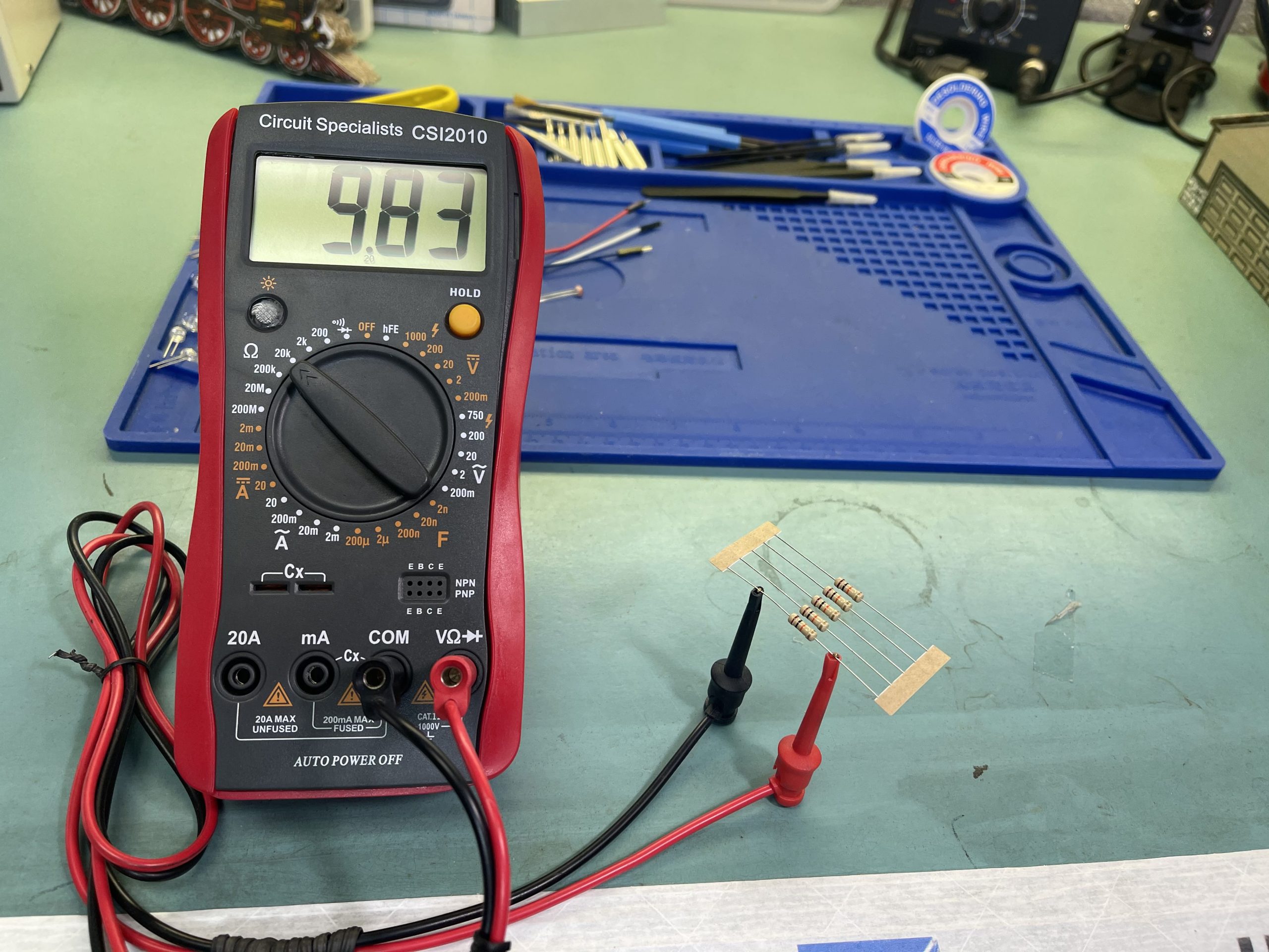
Digital multimeter
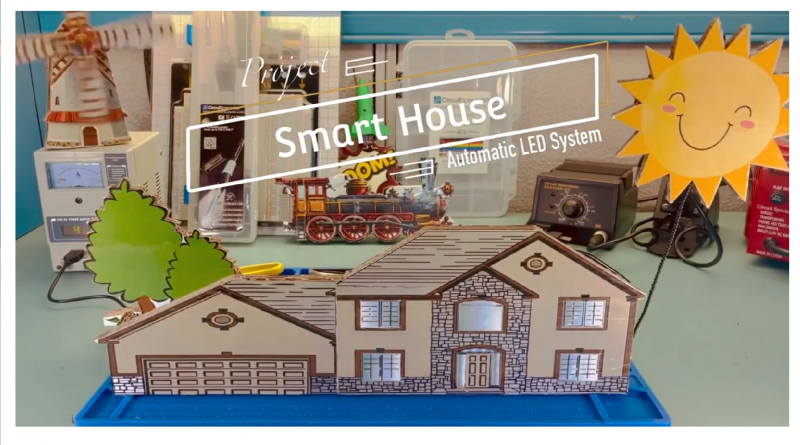
Automatic LEDs System
In today’s project, we will implement the “Sensing Light” lesson on page 23, which is the most basic step of a smart house, smart LED light system.
The light sensor will provide constant input from the environment and change the light level accordingly. The light system can be set to a specific mood such as dinner, movie, party, etc.
You can print the house template and glue it on cardboard with school glue, and then cut it out. This project also works with LEGO City Series and you would have to run the wire internally within the building.
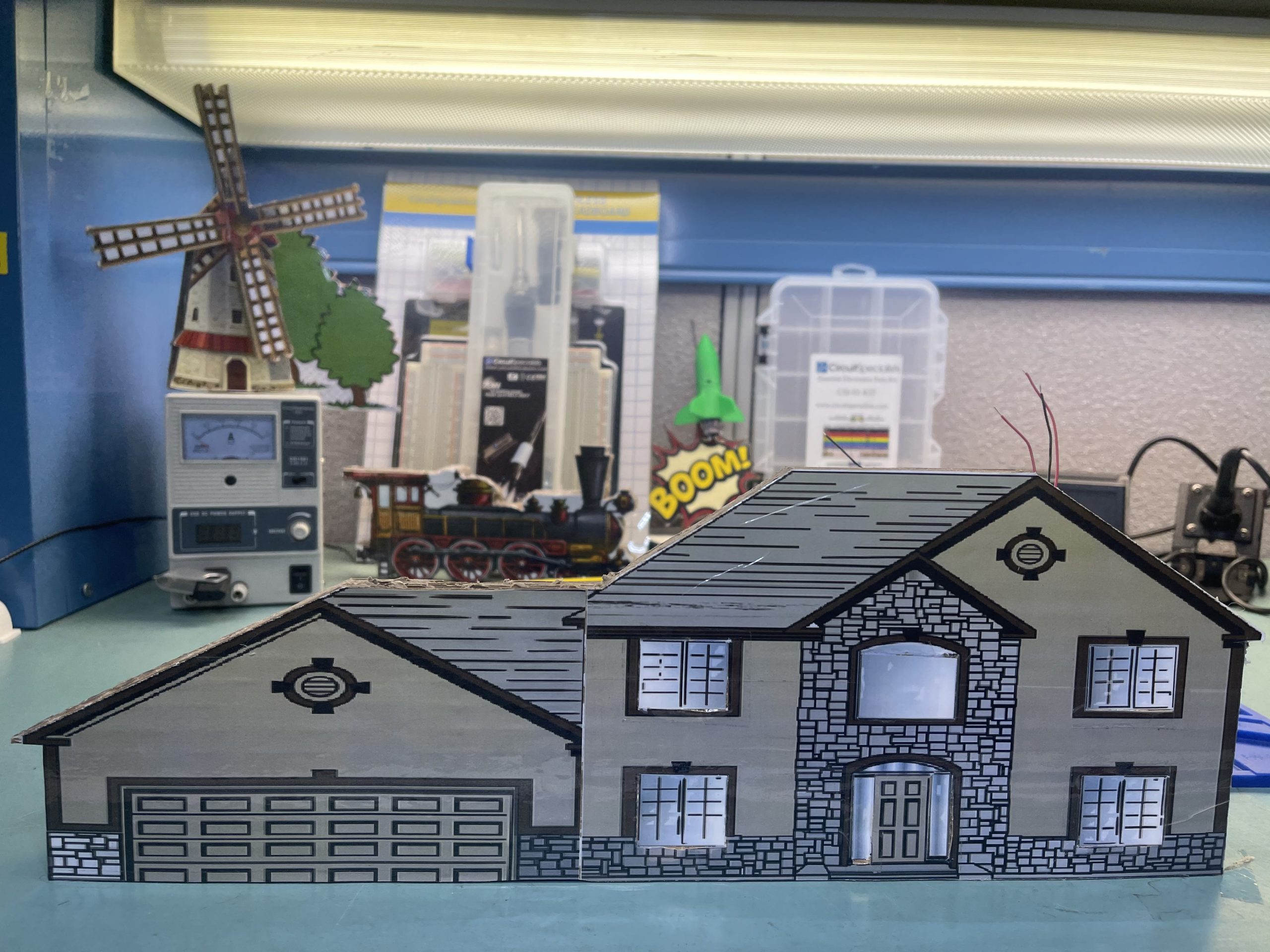
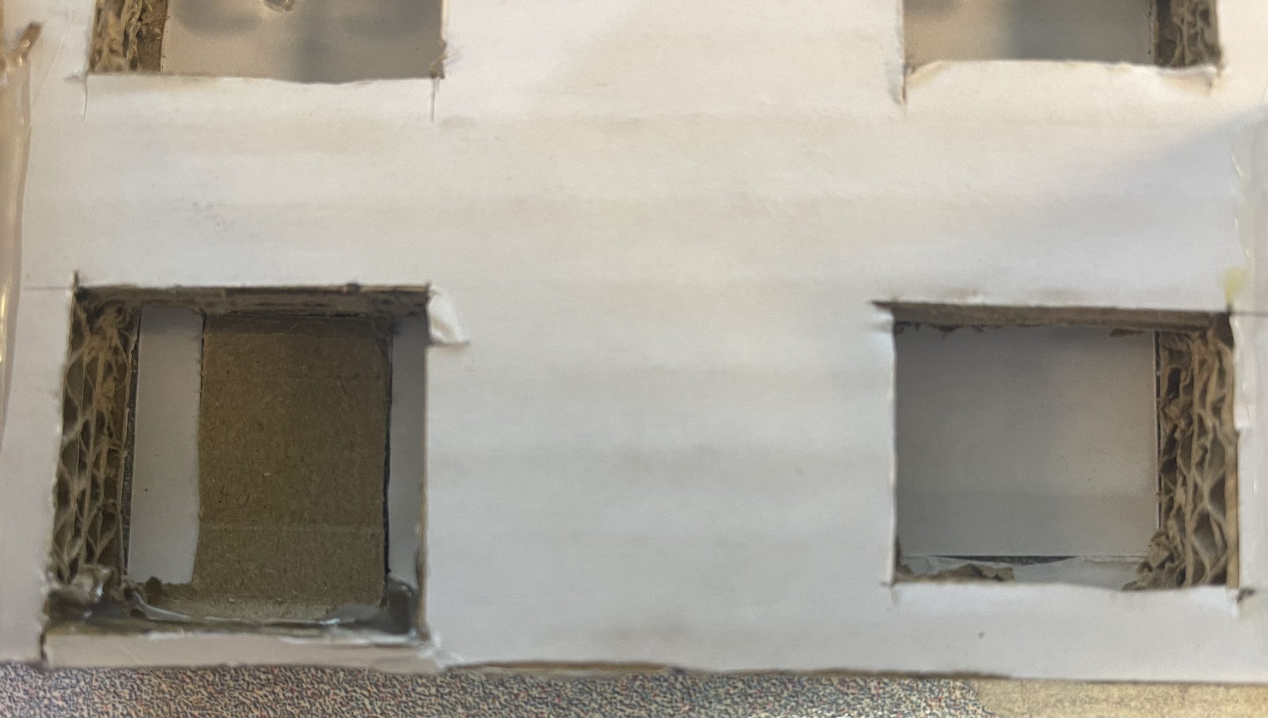
Now you need to cut the slot for the door and windows.
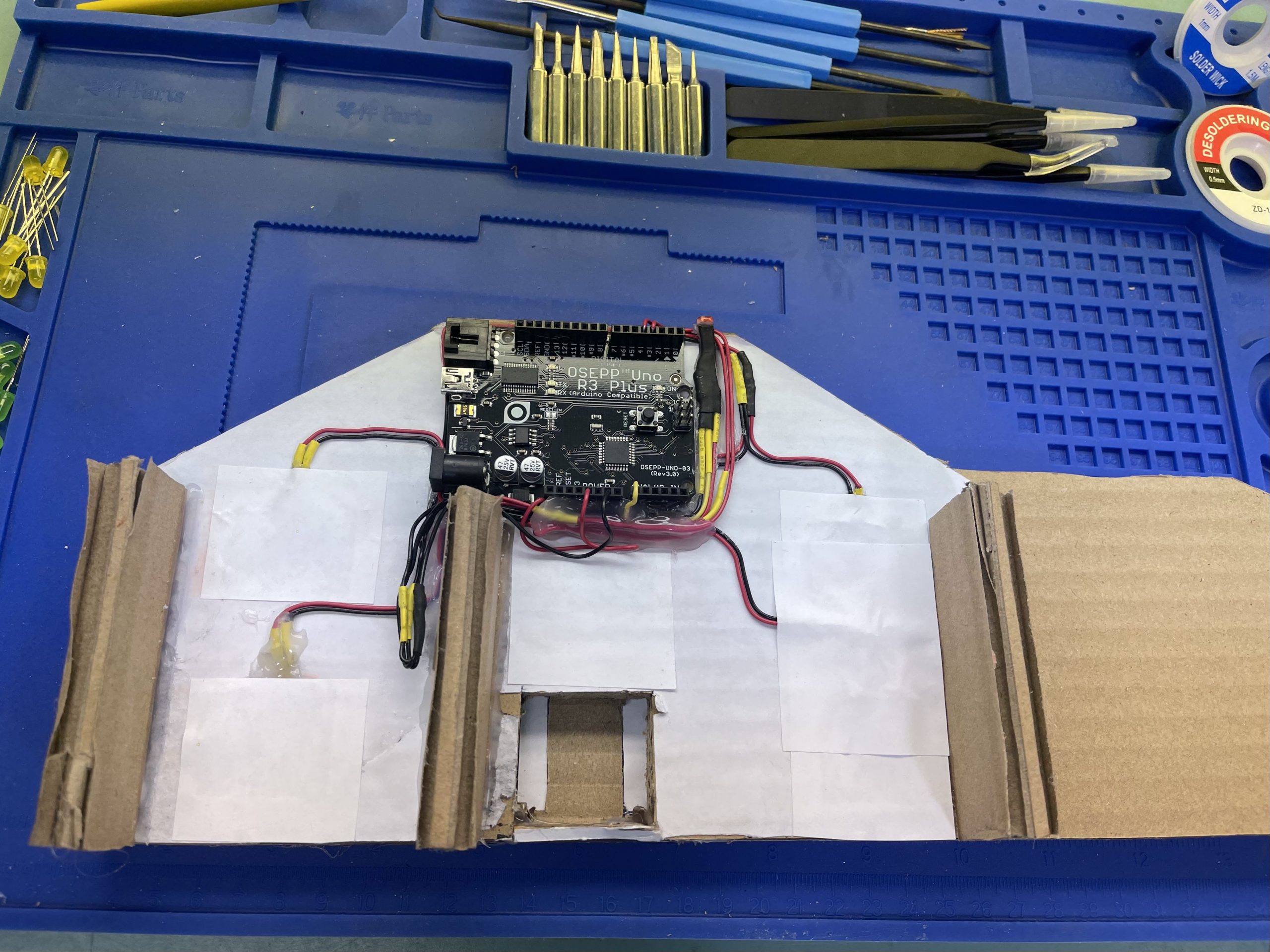
Install the LED lights for the first and second floors.
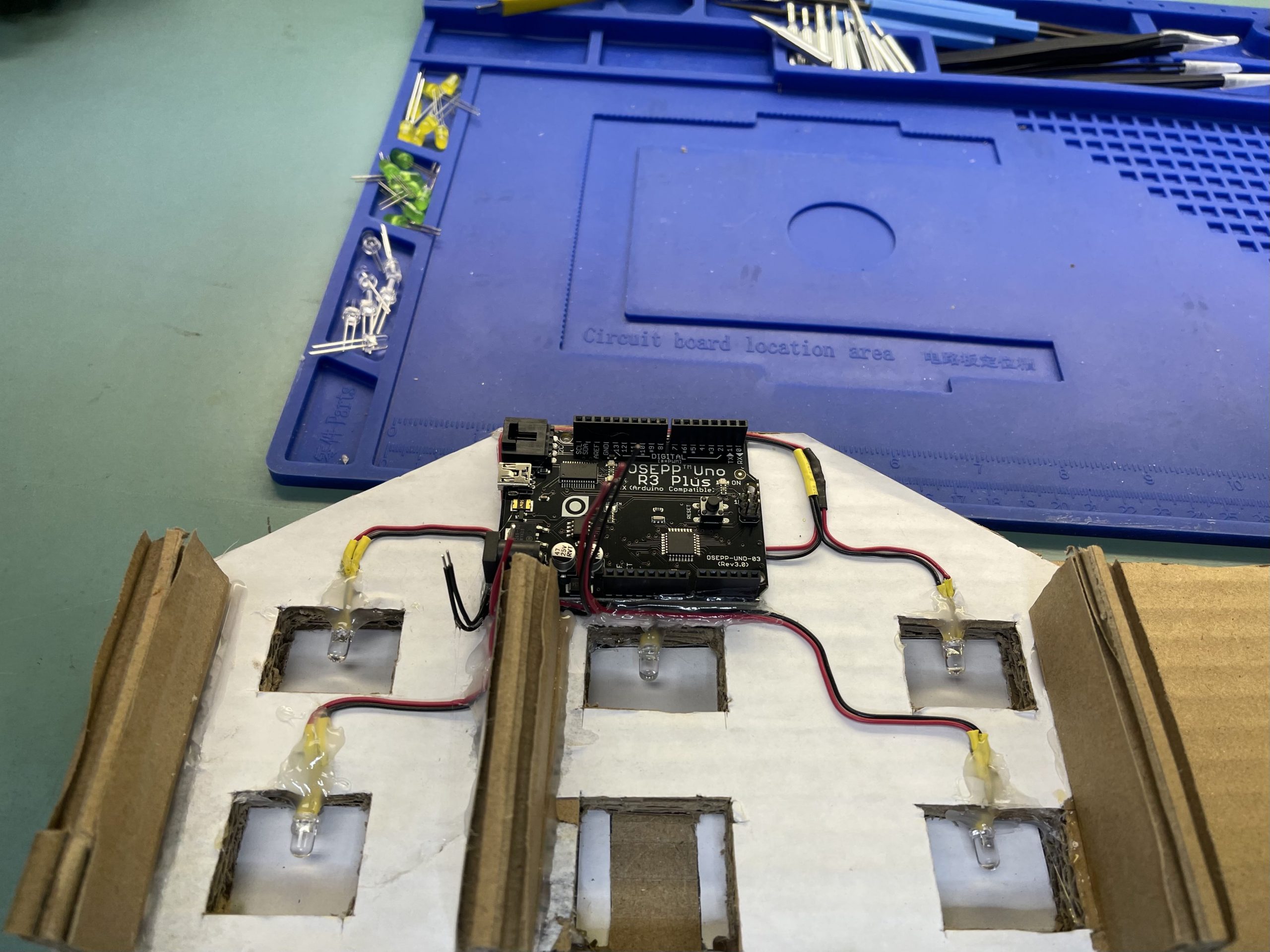
For reference, we used glue and a white piece of paper to close up the windows for better light distribution.
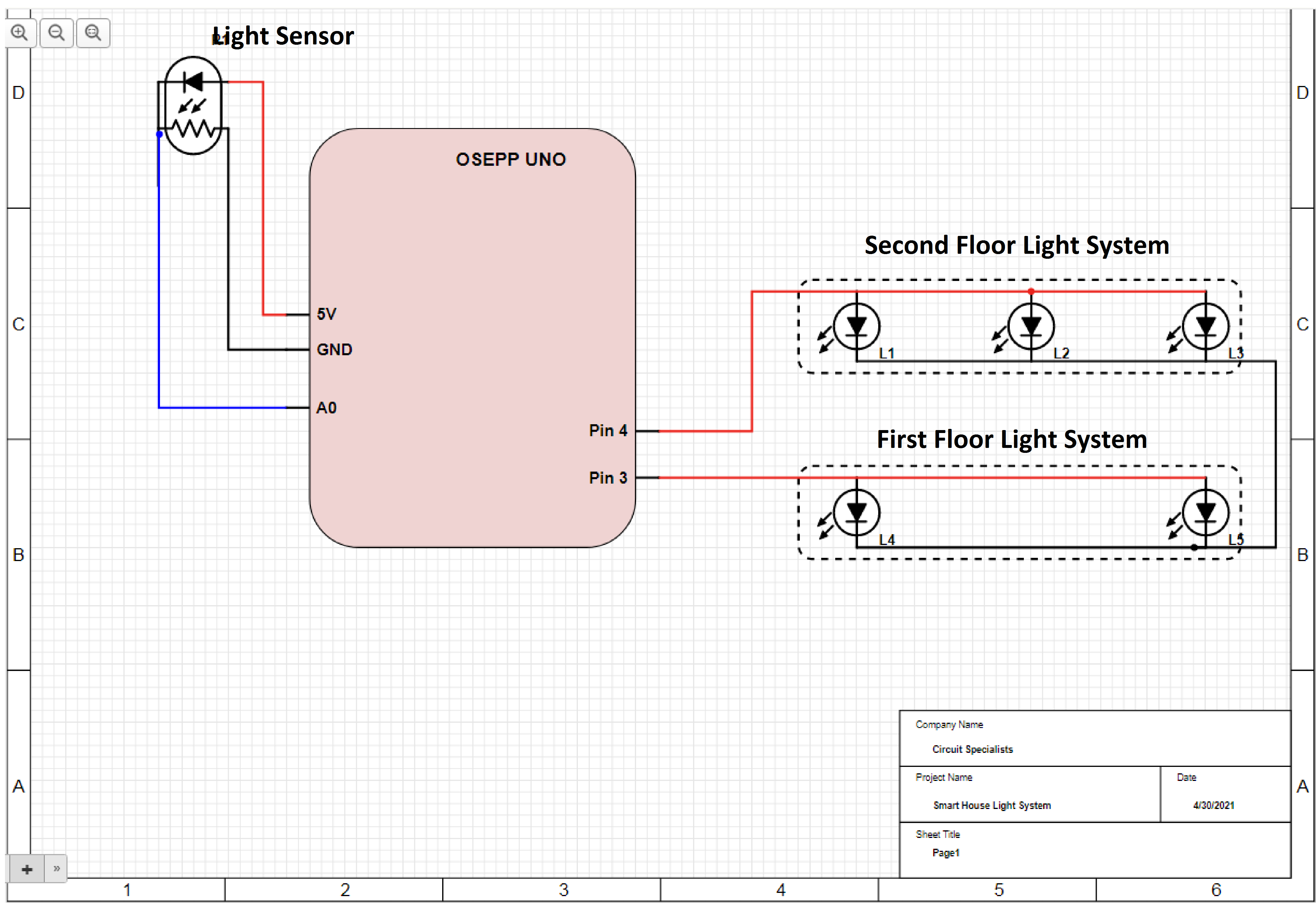
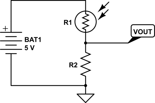
I will include a schematic below for the wiring.
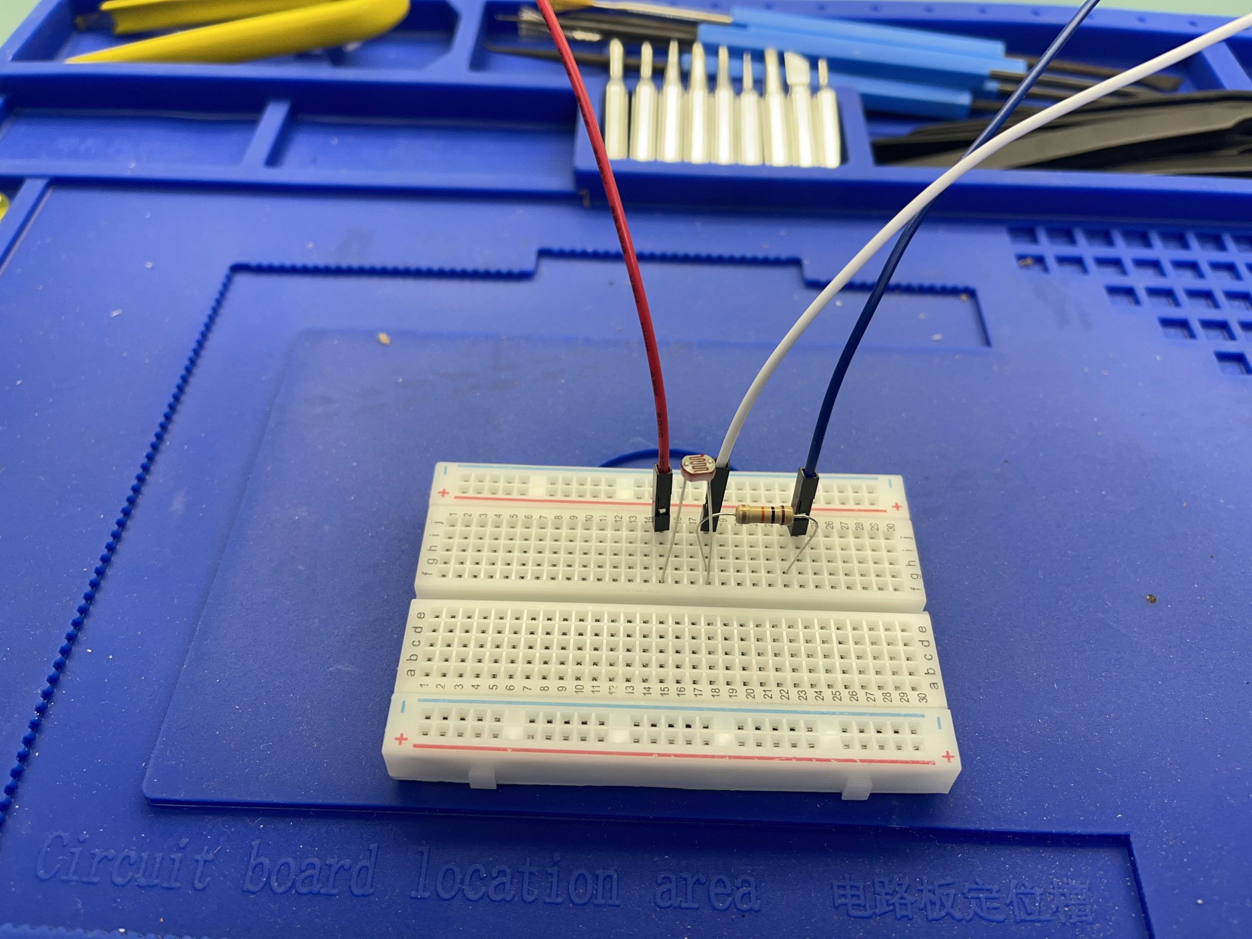
Assemble and Testing the Light Sensor
Required part for assembling the Light Sensor
I would test the resistor value to make sure that you have the correct 10K Ohm.
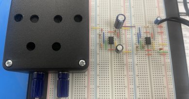
Light Sensor assembling
I will include the schematic below for reference.
Finally, connect the 3 wires to the Osepp Uno.
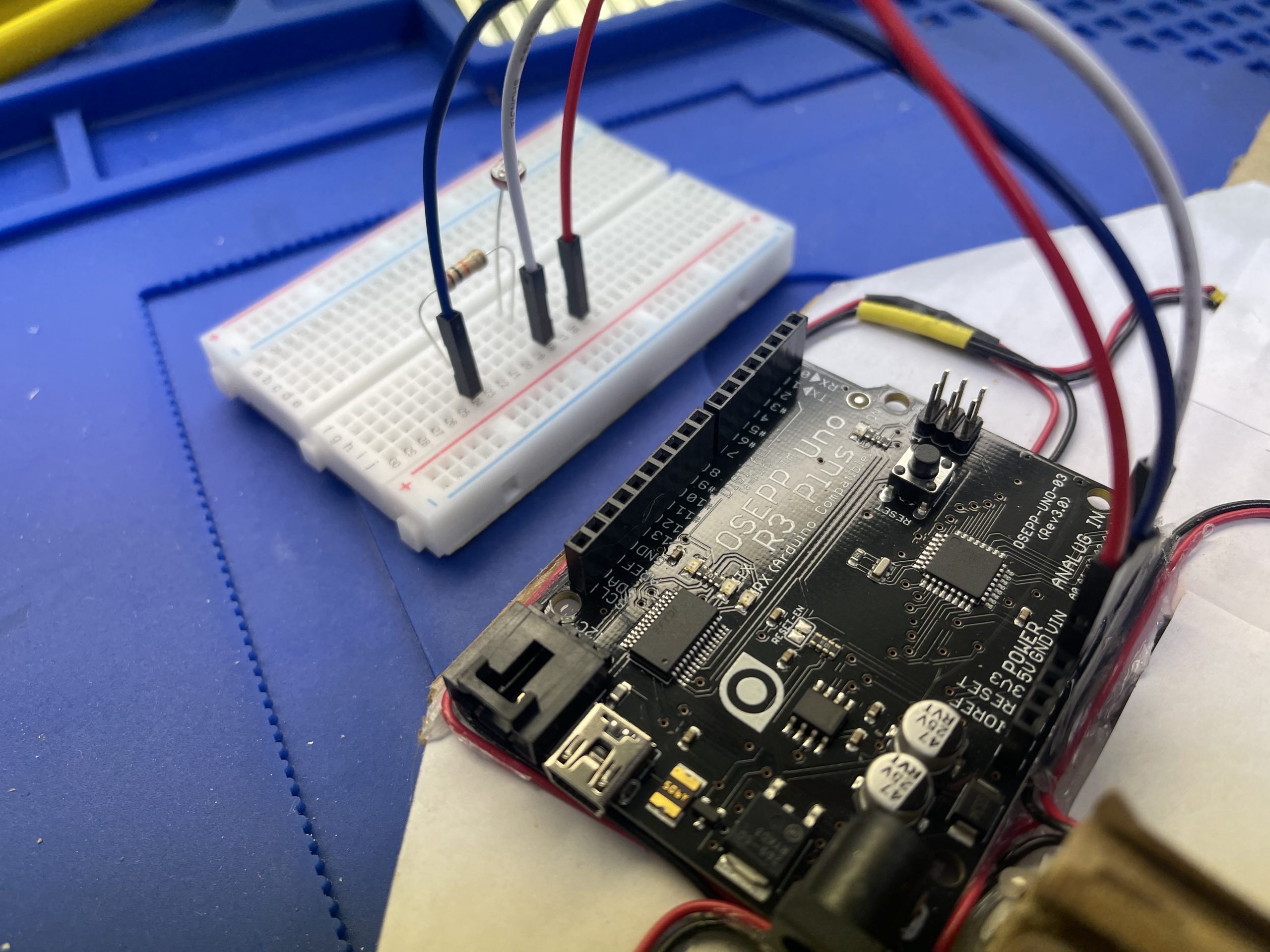
Upload the code to make sure the Light Sensor work as expected. I will attach a link below where you can download the example file.
http://osepp.com/files/osepp_201K.zip
Now, we need to make the sensor portable so that it works with our Smart House project.
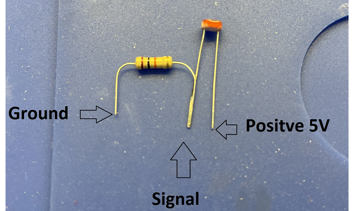
Solder the one side of the resistor to the photoresistor as the photo below, then solder the wire according to the code.
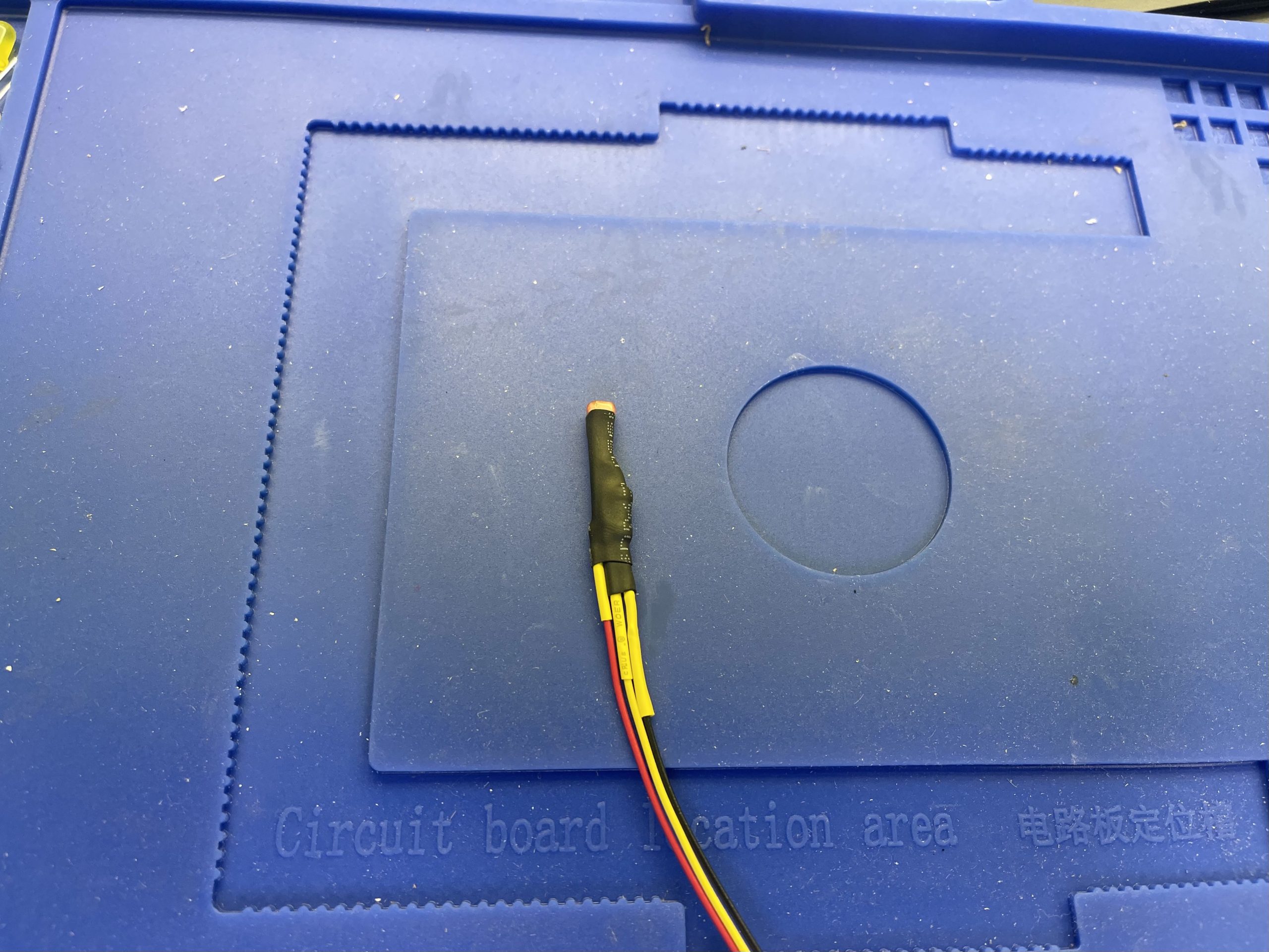
The Light Sensor should look like the picture below.
Pick a location toward the roof of the house for the best light input and connect the wire to the Arduino just like previous step.

Now we will change the code so that a certain light condition, the LED light system for our smart house will turn on or off accordingly.
//Project: Smart House

int First_Floor_LED = 3;
int Second_Floor_LED = 4;


const int sensorMin = 0;
// sensor maximum, discovered through experiment
const int sensorMax = 800;

// the photocell voltage divider pin
int photocellPin = A0;

void setup()
{
    // set up serial at 9600 baud
    Serial.begin(9600);
    pinMode(First_Floor_LED, OUTPUT);
    pinMode(Second_Floor_LED, OUTPUT);
}

void loop()
{
    int analogValue;
    int range;

// read our photocell
analogValue = analogRead(photocellPin);
// map the sensor range to a range of four options
range = map(analogValue, sensorMin, sensorMax, 0, 3);

// do something different depending on the
// range value
switch (range)
{
    // Dark turn on the light
    case 0:
        Serial.println("dark");
        digitalWrite(First_Floor_LED, HIGH);
        digitalWrite(Second_Floor_LED, HIGH);
        break;
    // Dim turn on the light
    case 1:
        Serial.println("dim");
        digitalWrite(First_Floor_LED, HIGH);
        digitalWrite(Second_Floor_LED, HIGH);
        break;
    // Medium turn off the ligh
    case 2:
        Serial.println("medium");
        digitalWrite(First_Floor_LED, LOW);
        digitalWrite(Second_Floor_LED, LOW);
        break;
    // Bright Turn off the ligh
    case 3:
        Serial.println("bright");
        digitalWrite(First_Floor_LED, LOW);
        digitalWrite(Second_Floor_LED, LOW);
        break;
}

// wait 0.25s before reading the photocell again
delay(250);
}
Below would be the demonstration of this add on feature for the Smart House
Conclusion
The Autonomous LED Light system is just the beginning of the Smart House project. There will also be motion control, security systems, and much more in future projects. That is not to overlook the importance of an intelligent LED light system in a Smart House. The house of the future will always make the occupants feel welcome after a long day of work, or changing the mood of the house for a welcome home party. Furthermore, the ability to turn the light on and off from an app could add another layer to the security overall.