How To Make An 8×8 LED Matrix
Learn how to make an LED matrix controlled by an Arduino.
Scroll down further for step by step photos and more details.
- You’ll need the following parts: a prototyping board, (2) 8 pin headers, (8) 200 ohm resistors and (64) red LED bulbs.
- Arrange the LEDs in the board according to the design you’ve chosen: either common row anode or common row cathode.
- Solder the LEDs to the board, being careful to not to cross any of the anode or cathode leads.
- Attach the 8 pin headers to feed power to the LEDs, be sure to place a 200 ohm resistor in line with each positive power lead.
- Test your board for continuity with a multimeter.
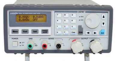
- Attach power to the 8 pin headers.
Today we will be starting our adventure into the deeply complex, yet totally incredible world of LED Matrices. This post is the first of an entire Arduino Matrix Programming series by Circuit Specialists.
First things first, what the heck is an LED matrix, and how does it work??
Simply put, an LED matrix is a grid of lights arranged into rows and columns. LED stands for Light Emitting Diode, so like with other diodes, electricity flows through it in only one direction – from anode(+) to cathode(-); doing so illuminates the light.
By arranging the anodes (positive side) and cathodes (negative side) in a particular way, we can achieve a matrix and call upon each LED individually by sending high and low signals from our arduino device.
Led matrices come in two arrangements. Common-row anode (left) and common-row cathode (right).
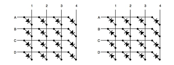
The difference between these two configurations determine how you would call on a specific LED. With common-row anode (left), the current sources (positive voltage) are attached to rows A – D. Currents sinks (negative voltage, ground) are attached to columns 1 – 4.
Conversely, with common-row cathode (right) the current sinks (negative voltage, ground) are attached to rows A – D and currents sources (positive voltage) runs through columns 1 – 4.
Applying this knowledge, to light the top-right LED (A,4) in a common-row cathode matrix you would feed positive voltage to column 4 and connect row A to ground.
We will be building this arrangement of common-row cathode matrix in this tutorial.
Step 1: The Parts
To build this matrix, we will need a few things to get us started.
2 – 8 Pin Headers
8 – 200ohm resistors
64 – Red LEDs
Some other essential supplies include: Soldering iron, Solder, Desoldering wire / rosin flux (just in case), wire (we recommend 2 different colors to stay organized), Heat shrink tubing (optional). We also recommend keeping a multimeter close by for testing purposes.
This will get the matrix built, later we will discuss what’s needed to get it running.
Step 2: The LEDs
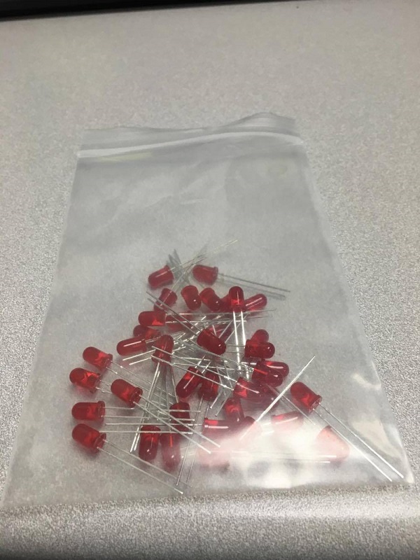
We’re going to be using a total of 64 5mm Red LEDs, it never hurts to have some extra though. Circuit Specialists stocks a pack of 100 5mm red LEDs you can get for only $1.65.
Make sure you note which side is the cathode(-) and the anode(+). Hint: it’s the long side on bulbs from Circuit Specialists.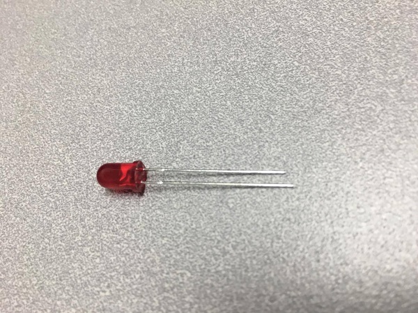 Or, you could always give it a quick test! Make sure you use a resistor!
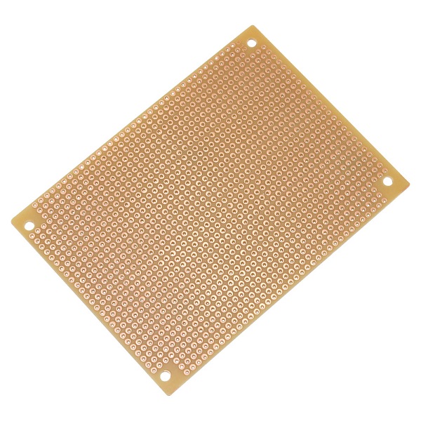
Now, we will begin arranging our bulbs on our perf board. We recommend the 3 x 4-1/4″ Solderable Perf Board model: 64-8934.
Step 3: Arranging the LEDs
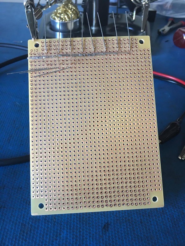
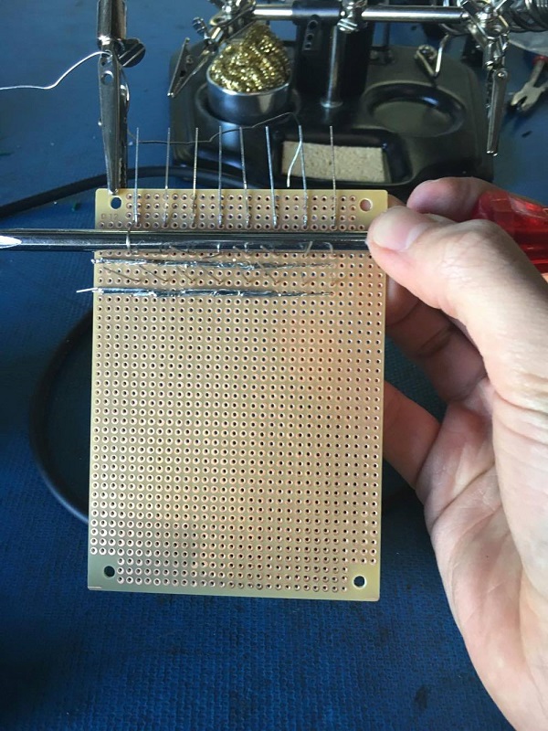
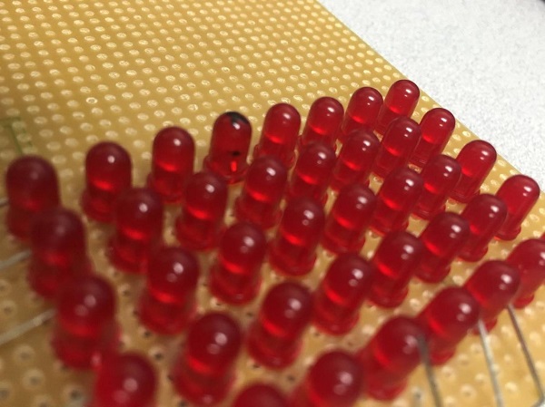
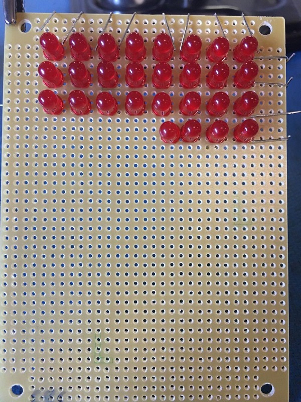
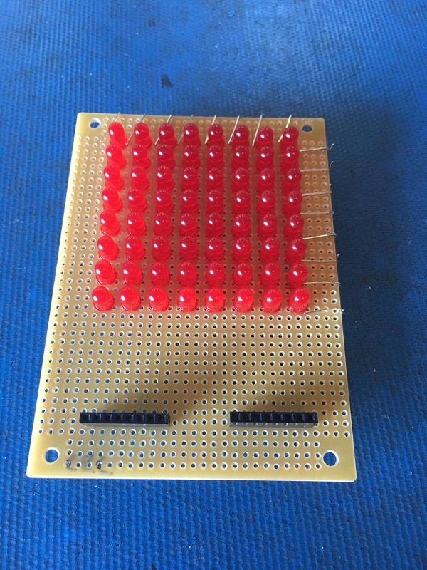
Because we’ve opted to use the common-row cathode arrangement in our matrix, we will be inserting the pins of the LEDs into the perf board in a particular fashion. It is extremely important to be diligent in this process.
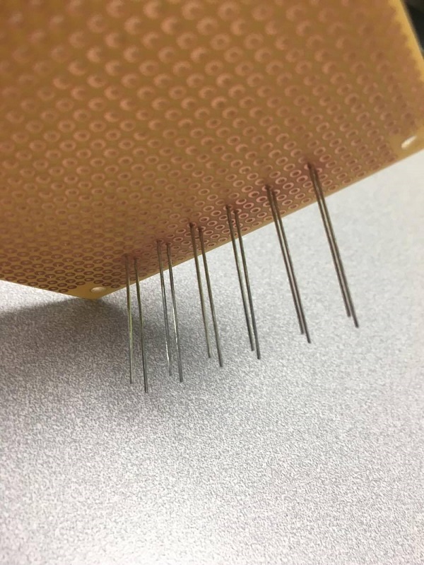
As you can see, we’ve opted to keep the long side (anode) on top, because we will be bending them vertically.
Now the fun begins….
Step 4: Soldering the Matrix
Our weapon of choice for the soldering portion of this build is the CSI Premier 75w Soldering Station. We will also be taking advantage of the immensely useful ZD10Y Helping Hand System (it makes ALL the difference).
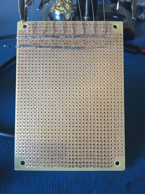
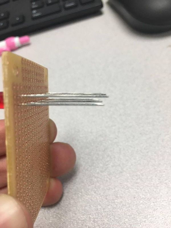
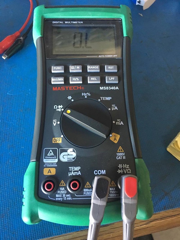
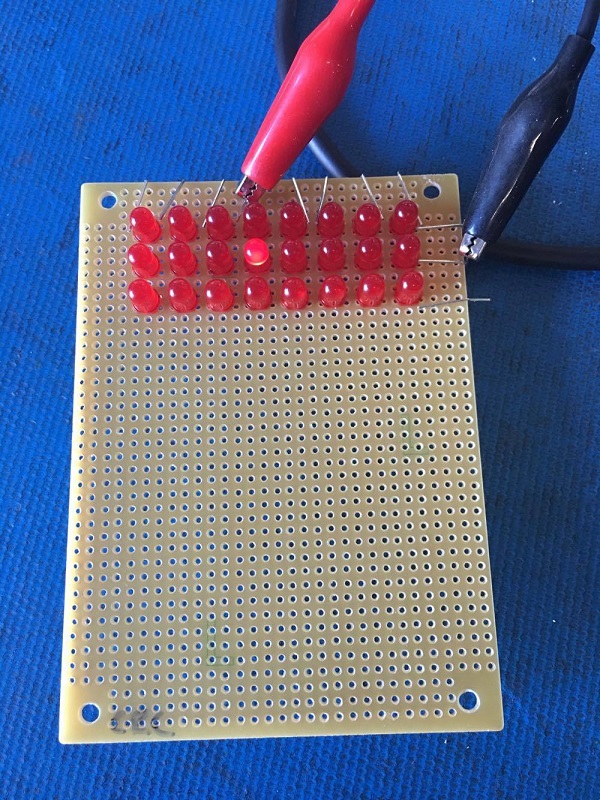
Once we’ve successfully soldered a row of cathodes, we can test their conductivity using a multimeter set to continuity mode.
 Leads set to each side of the row.
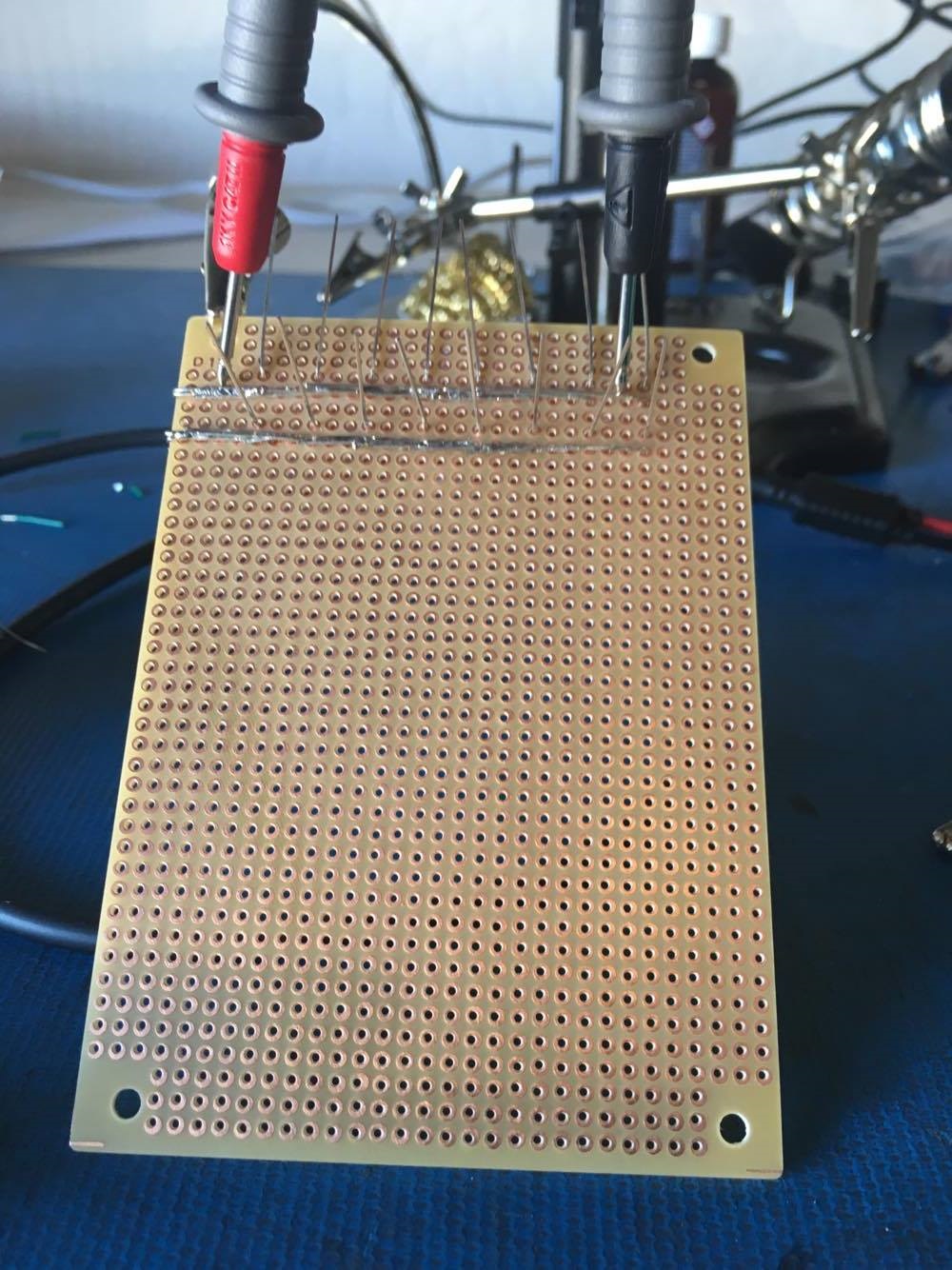
Any reading besides “OL” means you have a complete circuit.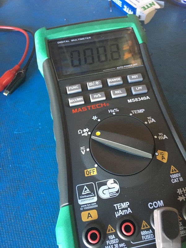
Checking our work along the way will save a TON of frustration later.
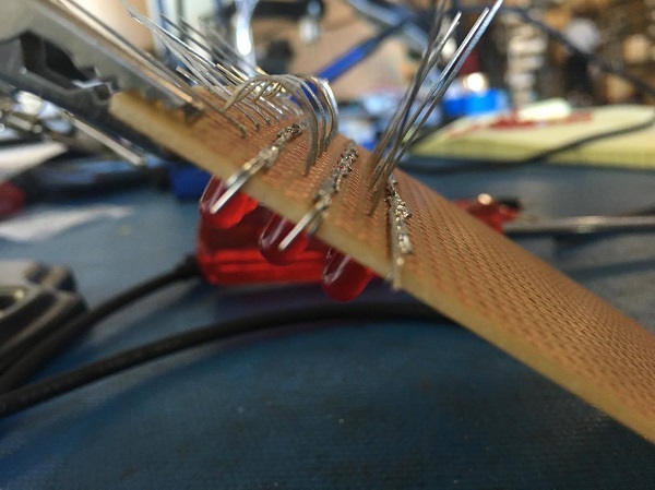
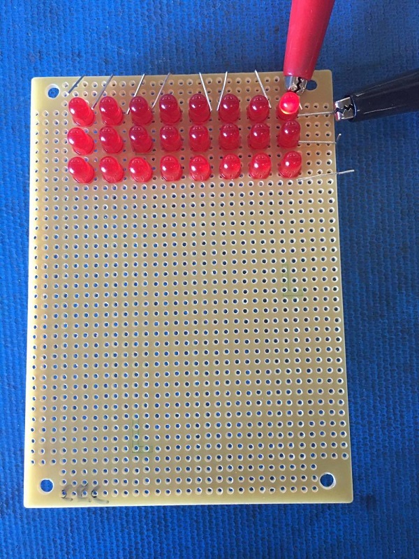
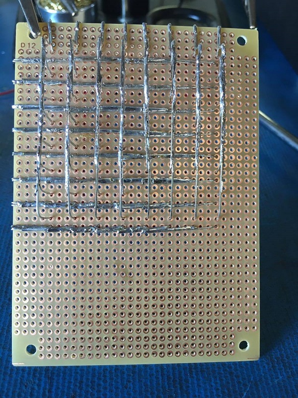
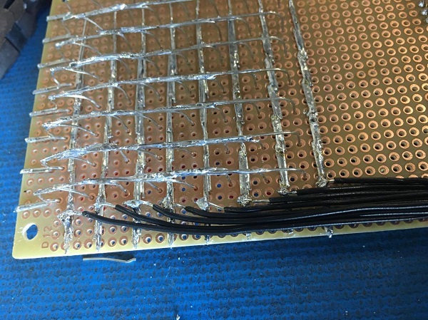
Now, we will start soldering the anode columns.
It’s absolutely critical that the anodes DO NOT touch the cathodes. Here, we’re using a screwdriver to assist with the bending process.
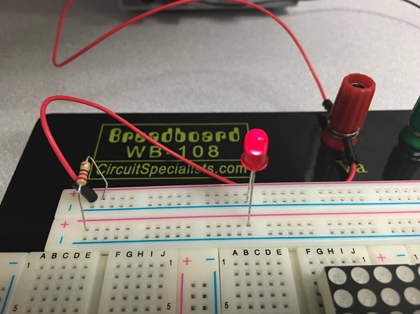
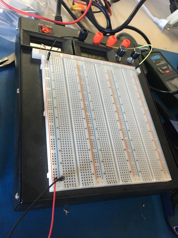
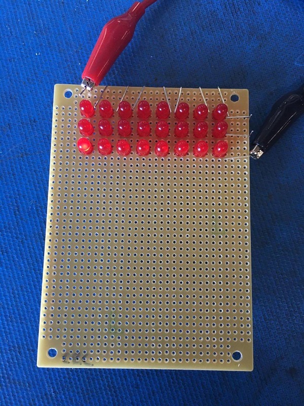
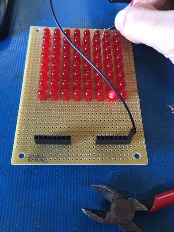
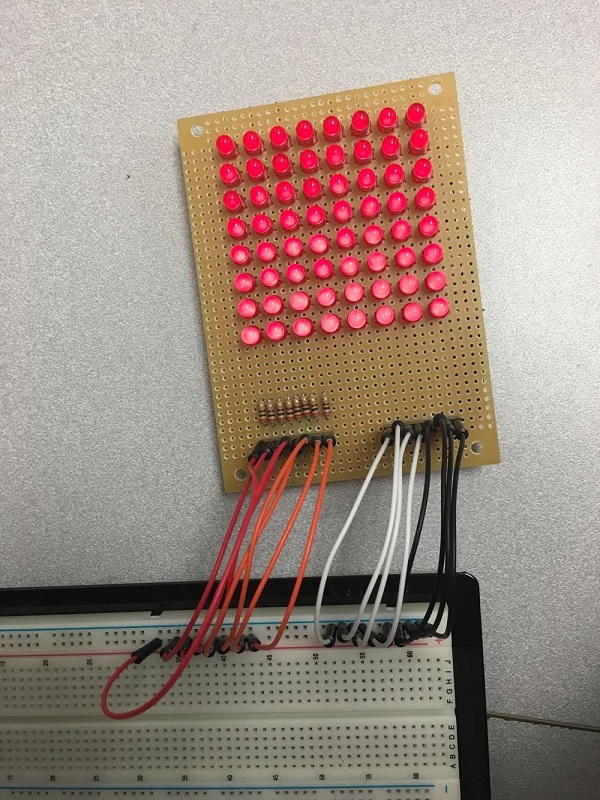
Now, let’s check our work again. Connect ground to your rows, and power to your columns… make sure you use a resistor!
A powered breadboard makes this process extra easy, but any breadboard will do.
This is what will happen if you do not use a resistor (blown bulb)….
Another easy mistake you might want to avoid (doh!)….
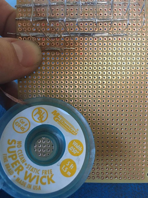
This is why desoldering wire and rosin flux are essential parts of your tool kit!
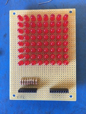
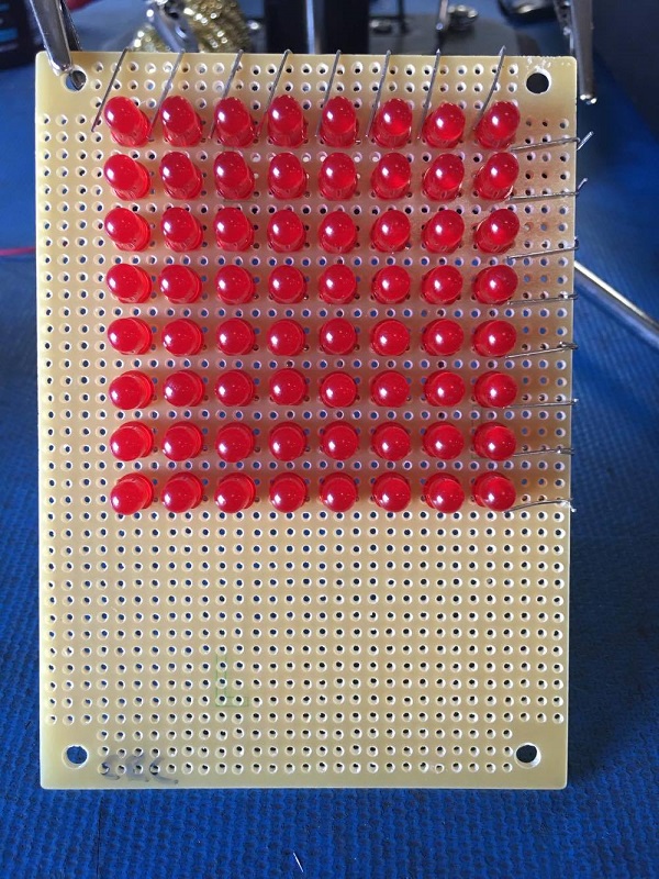
This is what it’ll look like when your soldering is complete.
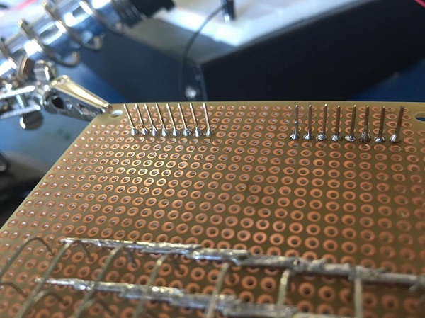
Step 5: Attaching the connectors
Now that our LEDs are arranged and we’ve tested each of the circuits, we will go ahead and attach the 8 pin headers to the perf board.
 Then we’ll add some solder to keep the headers secure.
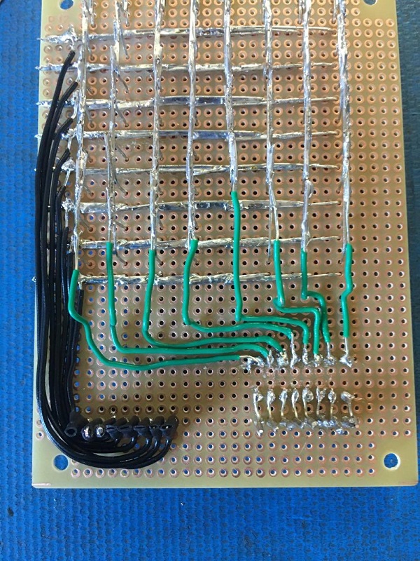
Now comes the (arguably) most difficult part of this build with regards to soldering skill…. connecting the pins to the rows and columns.
Keep in mind that the pins will be reversed when you flip the board over, so pay close attention to your work.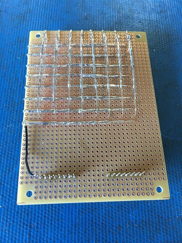
 Now we’ll test our connections one by one.
Then, we move on to the anode side. 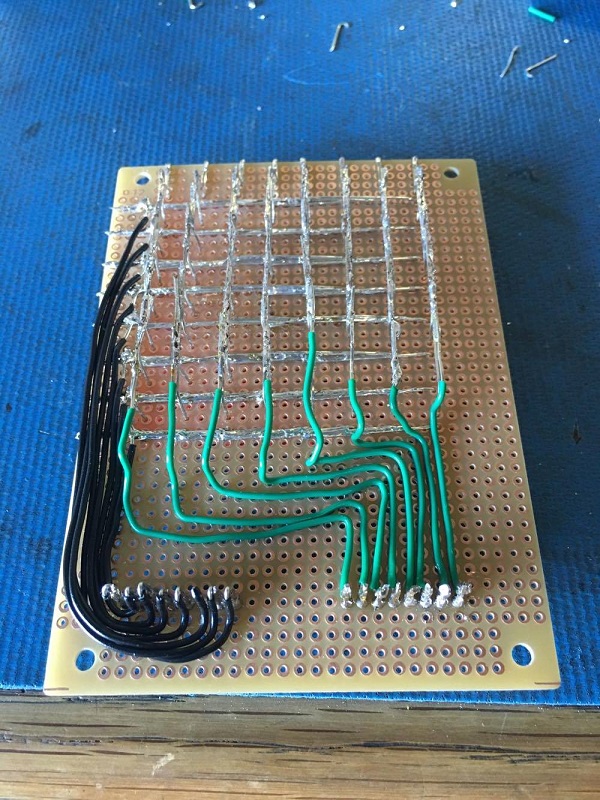
Then a little heat shrink to keep everything neat. 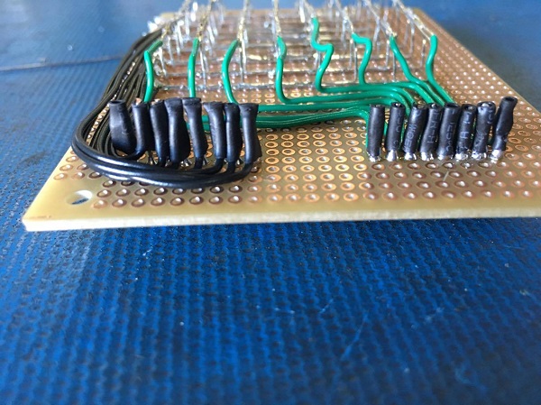
As you probably noticed, I initially forgot something very important…. THE RESISTORS!!
Try to avoid this, and get them in the power lines from the start.

Okay, much better… now we can power up the unit!
Looks great! Now we can start learning how to program the matrix using the OSEPP Uno R3 – Arduino compatible board!
We will begin this lesson next week. Make sure you subscribe to keep updated!


So how are the diodes connected.
I absolutely love this tutorial, it is very clear. I was wondering if you could do another one but with common anode RGB Led?